10
443 06 4003 00
Specifications subject to change without notice.
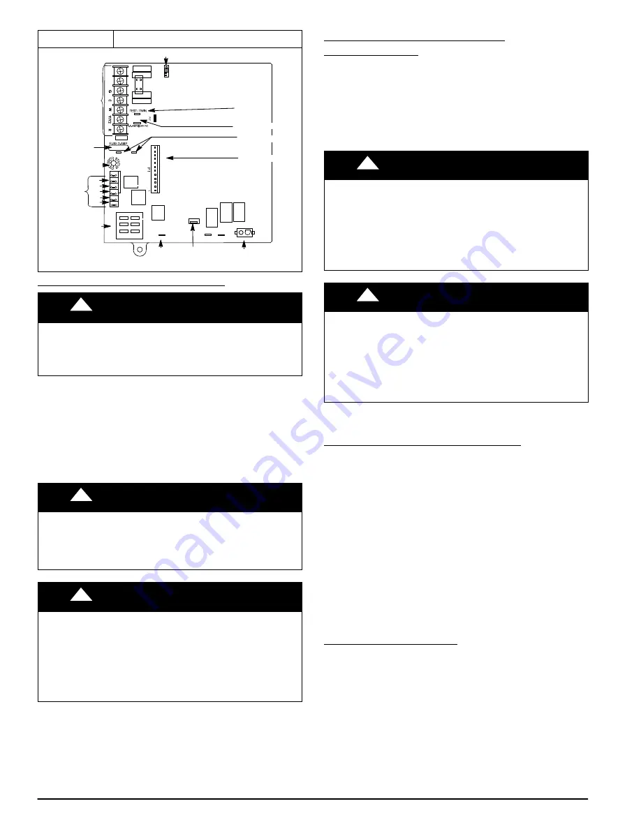
Figure 20
Single
−
Stage Furnace Control
ÏÏÏÏ
ÏÏÏÏ
ÏÏÏÏ
ÏÏÏÏ
TWINNING AND/OR
COMPONENT TEST
TERMINAL
P1
ï
LOW VOLTAGE MAIN
HARNESS CONNECTOR
TRANSFORMER 24VAC
CONNECTIONS
EAC TERMINAL
(115 VAC 1.0 AMP MAX.)
COOL
SPARE2
SPARE1
COM/BLUE
115
ï
VAC (L2) NEUTRAL
CONNECTIONS
24
ï
V THERMOSTAT
TERMINALS
HUMIDIFIER TERMINAL
(24
ï
VAC 0.5 AMP MAX)
3
ï
AMP FUSE
LED OPERATION &
DIAGNOSTIC LIGHT
24VAC/RED
BLOWER SPEED
SELECTION TERMINALS
BL
ï
1
XFMR
Y1
DHUM
HEAT OFF
ï
DELAY
12
0 180
90 150
Ï
ÏÏ
ÏÏ
ÏÏ
ÏÏ
ÏÏ
ÏÏ
ÏÏ
NEUTRAL
ï
L2
115 VAC (L1)
CONNECTIONS
L1
IND
P2
ï
HOT SURFACE IGNITOR (HSI) &
INDUCER MOTOR (IND) CONNECTOR
HEAT
FAN
HUM
24VAC
EAC
1 AMP
HSI
P2
COM
HEAT
COOL
FAN
SPARE 1
24V MTR
T
A
P
S
SPARE 2
REPRESENTATIVE DRAWING ONLY, SOME MODELS MAY VARY.
CHECK INLET GAS PRESSURE
!
CAUTION
UNIT DAMAGE HAZARD
Failure to follow this caution may result in unit damage.
DO NOT operate furnace more than one minute to check
inlet gas pressure, as conversion is not complete at this time.
NOTE
: This kit is to be used only when inlet gas pressure is
between 12.0
−
in. w.c. and 13.6
−
in. w.c.
NOTE
: Verify LP arrow on LP/NAT cap is pointed toward gas
valve.
1. Verify manometer is connected to inlet pressure tap on
gas valve. (See
)
2. Turn on furnace power supply.
3. Turn gas supply manual shutoff valve to ON position.
!
WARNING
FIRE, EXPLOSION, ELECTRICAL SHOCK HAZARD
Failure to follow this warning could result in personal injury,
death or property damage.
Gas supply MUST be shut off before disconnecting electrical
power before proceeding with conversion.
!
WARNING
ELECTRICAL SHOCK, FIRE OR EXPLOSION HAZARD
Failure to follow this warning could result in personal injury,
death or property damage.
Before installing, modifying, or servicing system, main
electrical disconnect switch must be in the OFF position and
install a lockout tag. There may be more than one disconnect
switch. Lock out and tag switch with a suitable warning label.
Verify proper operation after servicing.
4. Turn furnace gas valve switch to ON position.
5. Jumper R
−
W thermostat connections on control.
6. When main burners ignite, confirm inlet gas pressure is
between 11.0
−
in. w.c. and 13.6
−
in. w.c.
7. Remove jumper across R
−
W thermostat connections to
terminate call for heat.
8. Turn furnace gas valve switch to OFF position.
CHECK FURNACE AND MAKE
ADJUSTMENTS
1. Be sure main gas and electric supplies to furnace are off.
2. Remove 1/8
−
in. (3 mm) pipe plug from manifold pressure
tap on downstream side of gas valve.
3. Attach manometer to manifold pressure tap on gas
valve. (See
4. Turn gas supply manual shutoff valve to ON position.
5. Turn furnace gas valve switch to ON position.
!
WARNING
FIRE OR EXPLOSION HAZARD
Failure to follow this warning could result in personal injury
and/or death.
NEVER test for gas leaks with an open flame. Use a
commercially available soap solution made specifically for
the detection of leaks to check all connections. A fire or
explosion may result causing property damage, personal
injury or loss of life.
!
AVERTISSEMENT
RISQUE D’EXPLOSION ET D’INCENDIE
Le fait de ne pas suivre cet avertissement pourrait entraîner
des dommages corporels et / ou la mort.
Ne jamais examiner pour les fuites de gaz avec une flamme
vive. Utilisez plutôt un savon fait specifiquement pour la
détection des fuites de gaz pour verifier tous les connections.
Un incendie ou une explosion peut entrainer des dommages
matériels, des blessures ou la mort.
6. Check all threaded pipe connections for gas leaks.
7. Turn on furnace power supply.
GAS INPUT RATE INFORMATION
The gas input rate for propane is the same as for natural gas.
See furnace rating plate for input rate. (See
) The
input rate for propane is determined by manifold pressure and
orifice size.
The gas valve must be set for Low Heat first and then set for
High Heat on two
−
stage and variable
−
speed furnaces. Furnace
gas input rate on rating plate is for installations at altitudes up to
2000 ft. (610 M).
In the U.S.A.; the input rating for altitudes above 2000 ft.
(610M) must be reduced by 2 percent for each 1000 ft. (305 M)
above sea level.
In Canada; the input rating must be derated by 5 percent for
altitudes of 2000 ft. (610 M) to 4500 ft. (1372 M) above sea
level.
The Conversion Kit Rating Plate accounts for high altitude
derate.
SET GAS INPUT RATE
1. Jumper R and W thermostat connections to call for heat.
(See
)
2. Check manifold orifices for gas leaks when main burners
ignite.
3. Adjust manifold pressure to obtain input rate. (See
4. When main burners have ignited, confirm proper
manifold pressure is between 9.5
−
in. w.c. and 11.0
−
in.
w.c.. (See
5. If manifold pressure needs to be adjusted, use gas valve
adjustment key, factory
−
supplied in this kit or adhesive
pouch. (See
)


