


484 01 3700 01
5
REFRIGERANT LINES
Refrigerant lines must be configured per local building
codes and the guidelines outlined in the OD units
installation instructions.
NOTE
: The filter dryer should be placed just before the
indoor unit.
Connect Refrigerant Liquid and Suction Lines
For matched and mismatched systems, use line sizes
recommended in outdoor unit Installation Instructions.
The coil can be connected to outdoor units using accessory
refrigerant line sets or field--supplied lines of refrigerant
grade.
See Table 1 for coil connection tube size.
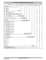
Table 1
COIL CONNECTION TUBE SIZE
inches (mm)
MODEL NUMBER
Liquid
Suction
ENH4X24(C,T)17A
3/8 (10)
5/8 (16)
ENH4X30(C,T)17A
3/8 (10)
3/4 (19)
ENH4X31(C,T)17A
3/8 (10)
3/4 (19)
ENH4X36(C,T)17A
3/8 (10)
3/4 (19)
ENH4X42(C,T)21A
3/8 (10)
7/8 (22)
ENH4X43(C,T)21A
3/8 (10)
7/8 (22)
ENH4X48(C,T)21A
3/8 (10)
7/8 (22)
ENH4X60(C,T)24A
3/8 (10)
7/8 (22)
ENH4X61(C,T)24A
3/8 (10)
7/8 (22)
UNIT DAMAGE HAZARD
Failure to follow this caution may result in product
damage.
To avoid valve damage to the refrigerant control device
while brazing, valves must be wrapped with a
heat--sinking material such as a wet cloth.
CAUTION
!
1. Remove cabinet access door.
2. Remove rubber plugs from coil stubs using a pulling
and twisting motion. Hold coil stubs steady to avoid
bending or distorting.
3. Wrap TXV and nearby tubing with a heat--sinking
material such as a wet cloth.
4. Fit refrigerant lines into coil stubs. Wrap a heat sinking
material such as a wet cloth behind braze joints.
5. Use 1/2 psig Nitrogen purge in the suction and out the
liquid line.
6. Braze using a Sil--Fos or Phos--copper alloy. Do not use
soft solder.
7. After brazing, allow joints to cool. Slide rubber grommets
over joints. Position tubing at center of each grommet to
ensure an air seal around the tube.
8. Always evacuate lines and reclaim refrigerant when
making connections or flaring refrigerant lines. Leak
check connections before insulating entire suction line.
9. If outdoor equipment will not be installed until a later
date, braze liquid and suction lines closed outside. Add
a Schraeder port test fitting to the suction line outside.
CONDENSATE DRAIN LINE CONNECTION
PROPERTY DAMAGE HAZARD
Failure to follow this caution may result in property
damage.
When installing over a finished ceiling and/or living area,
install a field--fabricated secondary condensate pan
under the entire unit.
CAUTION
!
The coil is designed to dispose of accumulated water
through built--in condensate drain fittings. It is recommended
that PVC fittings be used on the condensate pan. Do not
over--tighten. Finger tighten plus 1--1/2 turns. Be sure to
install plastic plug in unused condensate drain fitting. Two
3/4 inch female threaded pipe connections are provided in
each coil condensate pan.
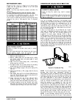
A trap is not necessary on the condensate line. Consult
local codes for additional restrictions or precautions. If local
codes require a trap then the following guidelines are
suggested to assure proper drainage. Install a trap in
condensate line of coil as close to the coil as possible. Make
trap at least 3 inches (76 mm) deep and no higher than the
bottom of unit condensate drain opening (See Figure 9).
Pitch condensate line 1 inch (25.4 mm) for every 10 feet
(3m) of length to an open drain or sump. Make sure that the
outlet of each trap is below its connection to condensate
pan to prevent condensate from overflowing the drain pan.
Prime all traps, test for leaks, and insulate traps and lines if
located above a living area.
3” / 76mm
A08067
Figure 9 -- Condensate Trap
NOTE
: If unit is located in or above a living space, where
damage may result from condensate overflow, a
field--supplied, external condensate pan should be installed
underneath the entire unit, and a secondary condensate line
(with appropriate trap) should be run from the unit into the
pan. Any condensate in this external condensate pan
should be drained to a noticeable place. As an alternative to
using an external condensate pan, some localities may
allow the running of a separate 3/4 inch (19 mm)
condensate line (with appropriate trap) per local code to a
place where the condensate will be noticeable. The owner
of the structure must be informed that when condensate
flows from secondary drain or external condensate pan, the
unit requires servicing or water damage will occur. To further
protect against water damage, install a float switch to shut
the unit off if the water in the secondary pan gets too high.
NOTE
: To avoid drainage problems, test the primary drain
line by slowly pouring water into the pan. Check piping for