


User’s Information Manual
5
441 02 2001 06
Thermostat
There are many types and styles of thermostats. Most thermostats
control both heating and cooling functions and have a Fan Switch
with
AUTO
and
ON
settings. On
AUTO
, the Circulating Air Blower
will cycle on/off with the unit, on the heating speed unless a call for
cooling is initiated. Blower speed will correspond to the mode of
operation of the unit. If the Fan Switch is positioned to
ON
the blow-
er will run continuously.
In addition some thermostats are programmable with multiple set
backs. The set backs can be pre--programmed to lower or raise the
temperature automatically.
Be sure to become familiar with your thermostat.
Rating Plate
The rating plate contains important information for the service
technician and lists the complete model, manufacturing and serial
numbers. You should always provide all these numbers when re-
questing parts or if you need service. See
Figure 2 or Figure 3
for
rating plate location.
Door Interlock Switch
All the electrical power for the unit goes through the door interlock
switch. The interlock switch interrupts electrical power to the unit
when the blower door is removed. The unit will not operate until the
blower door is reinstalled.
Fan Control
The fan/delay control provides power to the circulating air blower
to keep it on until the unit cools down.
The fan off setting can be adjusted if the fan remains on long
enough that cool drafts are felt in the room after the furnace shuts
off.
The delay is set by moving a set of switches on the control. The
Wiring Diagram located on the inside of the blower door shows the
various delay combinations. Refer to
Figure 2 or Figure 3
for
location of the control.
If you are unsure how to set the Fan Control, contact a Qualified
Service Technician.
Electronic Ignition Module/Gas Valve
When the thermostat calls for heat it completes a circuit to the elec-
tronic ignition module. The module sends an electrical signal
which ignites the pilot, then opens the gas valve.
When the flame is firmly established the ignitor goes off. If there is
a malfunction, the gas valve automatically shuts off the gas.
Pressure Switches
The unit is equipped with one or two pressure switches that shut
down the unit under various flue conditions. The switches are con-
nected to the furnace by factory supplied tubing.
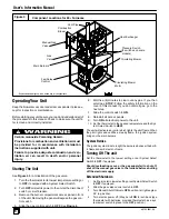
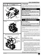
Circulating Air Blower
Rating Plate
Gas Valve/Ignition
Module
D
oor Interlock Switch
Pressure Switches
(some models have one)
Component Locations for Four Position Furnaces 90+ Furnaces
Fan/Delay Control
Furnace Vent Pipe
(Vent Pipe Connection through
Side Panel on Some Models)
Combustion Air Blower
Vent Pipe Grommet
Primary Heat Exchanger
Secondary Heat
Exchanger
Figure 2
dwg 25--23--9a
Diagnostic Light
Manual Gas Valve
Vent Drain Fitting
3
/
4
²²²²
OD Transition Box Drain Hose
5
/
8
²²²²
OD Vent Pipe Drain Hose
Plastic Transition Box
Air Intake Pipe
(Dual Certified or Direct
Vent furnaces)
Condensate Trap
D C Motor Control
(some models)
Representative drawing only, some models may vary in appearance.


