Mikhail Sleptso
v
6-04-'12
A4
110-01
1. Form:
170 x 120 mm
double sided printing, stapled booklet.
2. Fold
twice
to fit in box.
UTC Fire &
Security
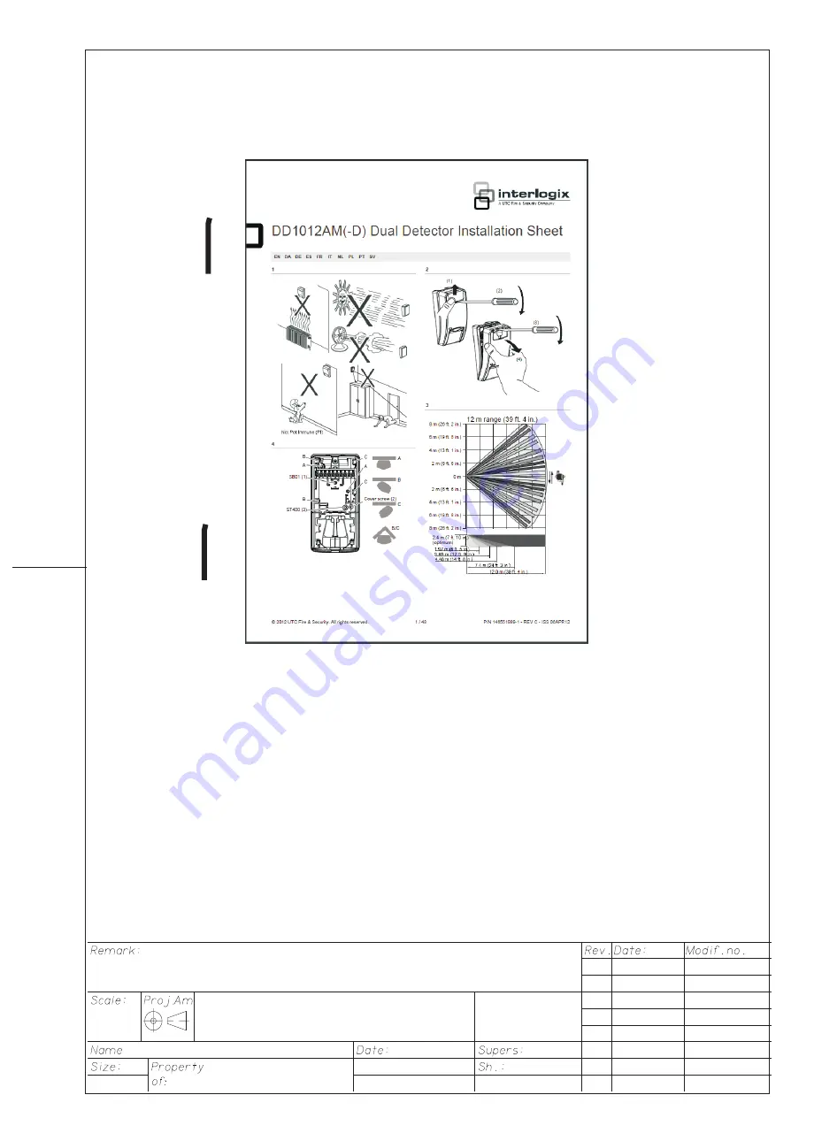
Manual DD
1
0
12AM
White paper: 75 gr/m, progresso; overprint black.
14
6551
999-
1
1
A
15 - 12 - '11
B 20 - 01 - '12
C 6-04-'12


