


PUBLIC ADDRESS POWER AMPLIFIER
5
PA-6312/6324/6336/6348
Rear Panel
Rear Panel
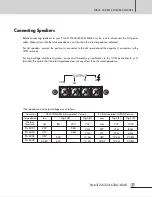
1. SPEAKER OUTPUT TERMINALS
These terminals are used to connect speakers to the unit. You may select either 4
Ω
or 8
Ω
conventional
operation, or High Impedance operation at either 70V or 100V. Make certain the combined impedance of
the speakers is equal to or higher than the rated load impedance of the amplifier.
Refer to page 7 for minimum load impedance and output voltage.
2. LEVEL CONTROL
This knob provides continuous control of the amplifier’s output level, from –12dB to 0dB (reference input of
0dB at 1V). Turning the knob clockwise increases the level, and turning it counter-clockwise decreases the level.
3. FAN VENTS
These vents provide hot air flow out of the unit. It is important to keep them free of obstructions, to prevent
the unit from overheating. It is also important to operate the unit in a dust-free environment.
4. AC POWER INPUT
Connect the supplied standard AC input cable here.
5. FUSE HOLDER
This holder contains the AC overload protection fuse. If the fuse has blown out, replace it with a fuse of the
same type and rating.
If the fuse continues to blow, refer servicing to a qualified service technician.
TEL
: (02)3493-4120
~
5
؎۾ېݕ@Z
܆ॄϿࠤ@Z@ؠ@ॕ
ЂʠϿ@Z
P
A
-
6
34
8
JH
09002-400
7
ďÖݖڜࣶ
E
RI
܆ܖڜ@Z@
܄ÿ՜ҿ۾Ͷ@Z
6
00
W
܄ÿ߾Ͷ@Z
4
8
0
W
܄ÿ۾ؖ@Z
A
C
220
V
6
0
H
z
H
P
F
ON
O
FF
~
A
C
I
N
P
U
T
220
V
6
0
H
z
F
U
S
E
:
T
8
A
L
/
2
5
0
V
D
C
I
N
P
U
T
24
V
B
A
L
A
N
C
E
D
I
N
P
U
T
1
V
/
10
K
L
I
N
K
I
N
P
U
T
(
A
D
J
)
12
d
B
0
d
B
100
V
(20
.
8
)
43
.
8
V
(4
)
O
U
T
P
U
T
C
O
M
A
B
7
0
V
(10
.
2
)
F
R
A
M
E
F
L
O
A
T
G
R
O
U
N
D
L
I
F
T
www
.inter-m.com
1
4
5
6
7
8
9
2
3


