


MODULAR DIGITAL AMPLIFIER
4
A-500
Front Panel
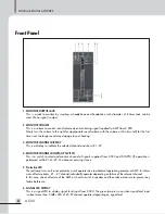
Front Panel
1. MONITOR OUTPUT JACK
This is a jack to monitor by inserting a headphone and headphone with diameter of 6.3mm Jack can be
used. Mono signal is output.
2. MONITOR VOLUME
This is a volume to control sound volume when monitoring signal supplied to AMP from Z-500.
Slowly turn the volume to the right for appropriate sound volume with the volume at Min (turn left) for the first
time since too large sound may damage to your hearing.
3. MONITOR CHANNEL DISPLAY
This is a display to indicate the selected channel and shows #1~#7.
4. MONITOR CHANNEL DOWN/UP SWITCH
This is a switch to select and monitor channel of signals supplied from Z-500 and DOWN/UP operation is
performed within #1-ch~#7-ch whenever pressing it once.
5. Protective LED
The red lamp turns on if inner protective circuit operates due to abnormal operation generates at AMP, to inform
warn of failure status. #1 ~ #7 channel individually operates depending on failure of the relevant channel.
In this case, check of failure of the AMP or short-circuit of a speaker and then take a measure to prevent any
failure before use.
6. SIGNAL LED DISPLAY
This is a signal LED to display signal level input from Z-500. The green lamp turns on when signal level input
is about more than -30dBv. LED of #1~#7channel operates depending on signal level.
7
8
1 2
3
4
5 6
Summary of Contents for A-500
Page 10: ...MODULAR DIGITAL AMPLIFIER 8 A 500 Applications Applications ...
Page 14: ...NOTE ...
Page 15: ...NOTE ...


