background image


22


the frames according with the setting of “Frames”, and the interval of the adjacent frame 
decided by the setting of “Interval”. 

14. 

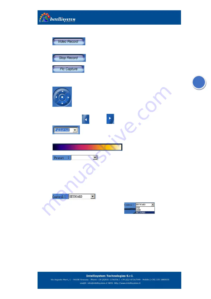
Click  to  start  recording  video.  The  record  will  be  saved  in 

compressed file. But the monitoring record could not be analyzed by the report software 

15. 

  Stop the monitoring record. 

16. 

Click  to  capture  current  image,  and  the  image  will  be  saved  in 

MPEG4  compressed  format,  but  the  images  could  not  be  analyzed  by  the  report 
software. 

17. 

  Simulating keyboard All the function could be operated by controlling this 

keyboard  with  keys  of  A.C.S.P.  In  menu  inactive  mode  click  middle  confirm  button  to 

autofocus, Click left

  and right 

key to manual adjust focus. 

18. 

To set the color scale.

 There are nine different palette selections. 

And the current selected palette will be displayed in the result table


19. 

To Yun terrace position preset. Click 

to display pull down 

menu(right figure): 

20. 


Call Preset

Recall the preset position data. 


Set Preset

To set the Yun terrace preset position data. 


Clear Preset

To clear the preset data. 

21. 

  Control  item 

selection. 

Click 

 to display options(right figure)


When you select one of the items the others 

item 

will 

be 

invalid. 


YUN

Select to control Yun terrace


LENS

Select  to  control  LENS,  Click  left/right  button  to  adjust  focus,  or  press  C 

button to autofocus. 


KEYBOARD

Select  to  control  the  camera.The  simulate  keyboard  has  different 

function in different option. 

Summary of Contents for ThermalTronix TT-1060MD-FTM Series

Page 1: ...ThermalTronix TT 1060MD FTM Series Thermal Imaging Camera User Manual...

Page 2: ...on or reflections from such devices may affect the accuracy of the camera readings or even harm or irreparably damage the detector whether the power supply of the camera is switch on or off Avoid inco...

Page 3: ...4 2 1 3 Vertical 9 4 2 1 4 Area 10 4 2 2 Level Span 11 4 2 3 Setup 12 4 2 3 1 Measure Set 12 4 2 3 2 Measure Correct 13 4 2 3 3 Analysis 14 4 2 3 4 Local Adapt 15 4 2 3 5 System Info 16 4 2 3 6 Fact...

Page 4: ...or to be set up as a stand alone system Real time color or voice alarm offer The TT 1060MD FTM is available in RJ 45 Ethernet models that are ideal for individual or network multiple camera installat...

Page 5: ...I O Port Digital TTL output input YUN terrace communication and user defined pins IO port output function recommended connection Output definition form left to right Item Power supply Serial port Com...

Page 6: ...ed connection Item VCC recommended 3 3V 5V 8V 12V RL recommended 10K VCE Output control pin We suggest adding amplifying circuit if the circuit drives high current component Normal state GPIO High imp...

Page 7: ...buttons to the spots position If camera is in horizontal measured mode press up down buttons to move the horizontal position press left right buttons to move reference point vertical contrarily If ca...

Page 8: ...age 3 Minimum temperature The minimum temperature of the color palette 4 Color palette To show the scale of the thermal image 5 Maximum temperature The maximum temperature of the color palette 6 Resul...

Page 9: ...ent menu objects This section describes the menu objects Figure 4 2 4 2 1 Temperature measurement mode Figure 4 3 Press confirm button to display the pull up menu Point to Measurement item by pressing...

Page 10: ...s the confirm button A spot will now appear on the screen The measured temperature will be displayed in the result table in the top right corner of the screen The temperature will show in shape with S...

Page 11: ...a curve will now appear on the screen The measured temperature will be displayed in the result table in the top right corner of the screen The line indicates the measured position and the curve is the...

Page 12: ...een The line indicates the measured position and the curve is the temperature distribution of the line The temperature will show in shape with LV YY to denote the intersection temperature of line and...

Page 13: ...n the screen The measured temperature will be displayed in the result table in the top right corner of the screen The temperature will show in shape with Ax YY Press A button to select the area and th...

Page 14: ...the area 4 2 2 Level Span Figure 4 9 Point to Level Span to and press the joystick to manually change level and span The level command can be regarded as the brightness while the span command can be r...

Page 15: ...creasing span 2 decreasing span 3 decreasing level and 4 increasing level 4 2 3 Setup This menu contains all the functions for changing the camera setup parameters This section describes the parameter...

Page 16: ...unless you turn on off the apparatus continually or the ambient temperature change quickly Briefly press left right button to adjust 0 1 press and hold down left right button to adjust 1 Ref Type On...

Page 17: ...ate to 0 5 meter if the distance within 10 meters Humidit y User defi ned To set the current environment humidity Increase or decrease the value by pressing the left right button 4 2 3 3 Analysis Figu...

Page 18: ...e isothermal temperature is 50 isothermal width is 2 and then the isothermal range will be 49 51 4 2 3 4 Local Adapt Figure 4 14 Point to Local Adapt and then press the confirm button to display the L...

Page 19: ...o changes can be made 4 2 3 6 Fact Default Figure 4 16 Point to FactDefault and press the confirm button to display the Reset prompt box Press confirm button to reset the camera to the factory setting...

Page 20: ...Need user set the IP address Mask etc FactDef Yes No Yes To load the factory default setting No Need user set the network parameter IP address To set the IP address Mask Appoint the Mask by net Gatew...

Page 21: ...operations TT 1060MD FTM_Client is accessional software you can use pc to control the camera by this software 5 1 Getting started Double click on to start up the software with the interface shown as...

Page 22: ...rresponding apparatus Figure 5 3 Move the mouse cursor to region 1 and click the mouse to active the region 1 and then click right button to display the pop out menu Point to the System and click to d...

Page 23: ...play on the screen if the connection is successful Figure 5 5 Click the work region 1 to zoom in the region 1 to whole work region Figure 5 6 5 2 2 Interface operation description 1 To start up the vi...

Page 24: ...for getting a more accurate measurement and optimal images 7 Freeze the image on the display 8 Click to quit the last operation 9 Click to make the apparatus enter sleep mode and disconnect the netwo...

Page 25: ...nfirm button to autofocus Click left and right key to manual adjust focus 18 To set the color scale There are nine different palette selections And the current selected palette will be displayed in th...

Page 26: ...e the mouse onto the monitoring frame Press the left key of the mouse while moving it until to a certain position and release the key The start point of the line is where you start moving the mouse an...

Page 27: ...he apparatus Note the IP address setup must same as the current apparatus Figure 5 8 To set the emissivity of spots line and areas To select the display temperature type of areas Figure 5 9 Click butt...

Page 28: ...r Reference the 4 2 3 3 Temp Unit F K To select the display unit Figure 5 11 Item Value Comments Measure Class 1 2 To select temperature range Refe Type 9 optional To select reference temperature type...

Page 29: ...rm Color Optional To select alarm color Figure 5 13 Item Parameter Comments MAC Addr Settled The unique MAC address of every apparatuses set by manufactory Auto Adjust Time User defined To set the aut...

Page 30: ...l To select the communication protocol with Yun terrace Optional PELCO D and YAAN Addr Spare address 5 4 Video play software Figure 5 16 Click to display a windows dialog box select the file that you...

Page 31: ...he play speed These buttons are used for controlling video play To record a section of the video You can set the save path via operate the setting dialog box To capture a frame image and save to hard...

Page 32: ...brate the camera for long time Calibrate the cameral After go back default setting the parameter different with camera and the client software It s necessary to reconnect the network after go back def...

Reviews: