background image


7


LED indicator


  IT-ES3020-IU-4GS series LED indicator light on the front panel .the function of each LED is described in the table as below: 

System status LED 

LED 

Indicator 

Description 

P1 

ON 

P1 connection regularly 

OFF 

P1 

Power 

supply 

have 

no 

connection or unwonted 

P2 

ON 

P2 connection regularly 

OFF 

P2 

Power 

supply 

have 

no 

connection or unwonted 

ALARM 

ON 

Power, port have alarm 

OFF 

Power, port have no alarm 

RUN 

ON/OFF 

Device unwonted 

Blinking 

Device working steadily, Blinking 

per second 

Link/Act 

1

16


ON 

100M port Established effective   

network connection 

Blinking 

100M  port  Network  in  activity 

status 

OFF 

100M  port  did  not  establish 

effective network connection 

Link/Act 

G1

G

4


ON 

1000M port Established effective   

network connection 

Blinking 

1000M  port  Network  in  activity 

status 

OFF 

1000M  port  did  not  establish 

Summary of Contents for IT-ES3020-IU-4GS Series

Page 1: ...and MDI MDI X self adaption It built in standard industry design all components are bas ed on Industry grade no fan low consumption can satisfied some kinds of requirements of industry field to achiev...

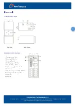
Page 2: ...DC 1 Running status indicator 2 Power supply indicator 3 Power supply alarm 4 1000M optic port SFP slot 5 10Base T 100Base TX Ethernet 7 4 bits power supply terminal block 8 Ground screw 9 Relay alarm...

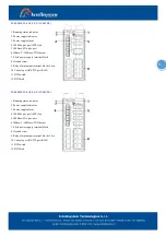
Page 3: ...Relay alarm output terminal block 2 bits 10 Console port RS 232 port RJ45 11 DIP switch 12 DIN Rail IT ES3020 IU 4GS 4F P 12 48VDC 1 Running status indicator 2 Power supply indicator 3 Power supply a...

Page 4: ...rent protection Reverse connection protection Voltage input range is 12 48VDC terminal block defined as V1 V1 V2 V2 Important notice 1 Power ON operation first of all insert power cable s terminal blo...

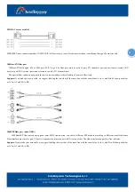
Page 5: ...tus of DIP switch Communication connector 10 100BaseT X Ethernet port The pinout of RJ45 port display as below connect by UTP or STP The connect distance is no more than 100m 100Mbps is used 100 of UT...

Page 6: ...of network effectively Suppose if you make your own cable we suggest labeling the two sides of the same line with the same letter A to A and B to B shown as below or A1 to A2 and B1 to B2 1000SFP fib...

Page 7: ...r supply have no connection or unwonted ALARM ON Power port have alarm OFF Power port have no alarm RUN ON OFF Device unwonted Blinking Device working steadily Blinking per second Link Act 1 16 ON 100...

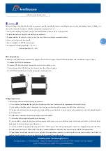
Page 8: ...Wiring Requirements Cable laying need to meet the following requirements 1 It is needed to check whether the type quantity and specification of cable match the requirement before cable laying 2 It is...

Page 9: ...Km Exchange attribute 100M forward speed 148810pps 1000M forward speed 1488100pps 100M maximum filter speed 148810pps 1000M maximum filter speed 1488100pps Transmit mode store and forward System excha...

Page 10: ...Installation DIN rail and wall mount Size W H D 160mm 130mm 70mm Weight 1016g Working environment Working temperature 40 85 Storage temperature 40 85 Relative Humidity 5 95 no condensation Standards E...

Reviews: