background image


Intellisense Systems Inc. 

Page 10


– Rev 02.25.21


  Micro Weather Station (MWS

®

) User Guide – Commercial Series 

OPTIONAL SETTINGS AND ADVANCED FEATURES


Optional Settings 


The optional settings control certain aspects of measurement timing and sampled parameters. They are stored 

in memory and will stay in the last user-defined setting upon power-up. 


GPS: 

GPS latitude and longitude can be enabled or disabled by the user. GPS is enabled from the 

factory by default, which will allow you to determine the unit’s location when reporting. If the location is 

not desired, it can be disabled. However, a GPS lock is still required upon powerup to obtain elevation 

and to obtain the proper system time for reported weather readings. GPS coordinates are reset upon 

each power cycle (via the physical power switch) and a re-lock is required upon each new power-up. 

GPS will also attempt a re-sync approximately once every 10 days of continuous operation to 

accomodate for station movement and to update the system clock.


Image Requests (C500/600 models only):

 A single image set can be requested or scheduled based on 

system time (with hourly images being the fastest). When hourly images are requested, they will always 
send at 56 minutes after the hour. The default setting is no images. 


Ceilometer (C600 models only):

 There are 3 ceilometer settings: “Disabled.” “Enabled,” and “Enabled 

Always.” The “Enabled Always” command enables users to take 4 ceilometer readings (in 15-minute 

intervals) regardless of what reporting mode the station is in, which may consume more power. The 

“Enabled” setting changes the number of ceilometer readings depending on reporting mode. The default 

setting is “Enabled.”


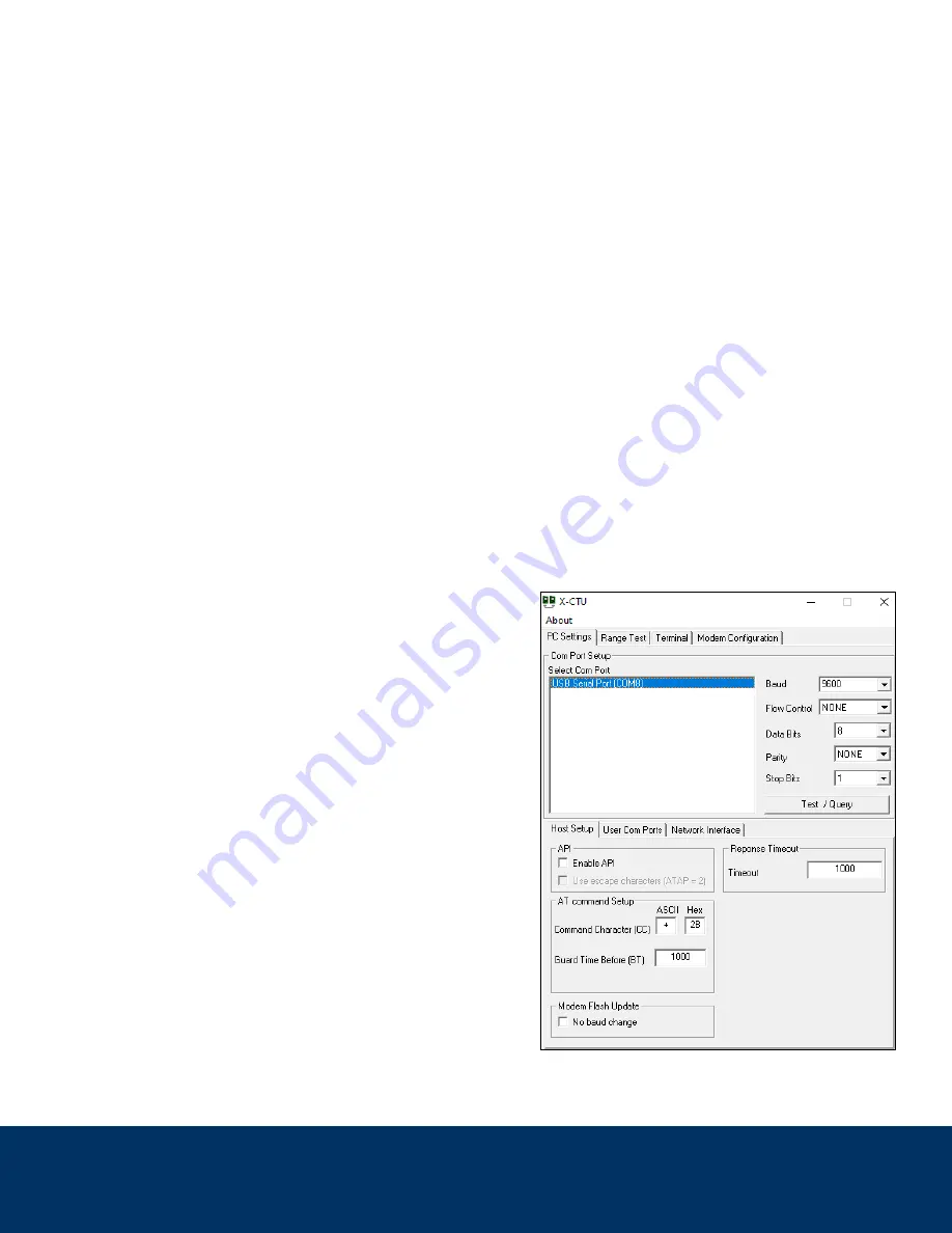
Raw Output Over Serial Connection


For advanced users or those using custom data processing 

software, the station output can also be viewed over serial 

USB connection in its raw format by plugging a MWS Power 

and Data Cable into the “DATA” port on the unit and plugging 

the receiving end into a standard USB Type-A port on your 

PC. The station will output over serial automatically at each 

sample time as defined in the reporting descriptions above. 

Output can be viewed on X-CTU or a similar serial terminal 

software with the settings shown below and COM port that 

coincides with the cable input. An example is pictured right: 


Summary of Contents for MWS Commercial C400

Page 1: ...Intellisense Systems Inc 1 Installation Guide 20600 Gramercy Place IG AWARE Flood 11 2019 Torrance CA 90501 1821 Revision A 310 320 1827 Micro Weather Station MWS User Guide Commercial Series...

Page 2: ...ions to follow The MWS Commercial Series At A Glance Series Name Commercial Model No C400 C500 C600 FEATURES Colors Available White Coyote Brown o o o Integrated Solar Panels Integrated NiCd Battery P...

Page 3: ...titude 18 Debris Accumulation C500 C600 models only 9 GPS Longitude 19 Cloud Height C600 models only 10 GPS Elevation These environmental parameters are determined using inputs from a combination of s...

Page 4: ...Install near any large objects that obstruct the unit from above Place the unit within 30 ft of any structures trees or boulders taller than the MWS Use a mounting solution that may cause the unit to...

Page 5: ...ubstrate to prevent the dislodgement or accidental tipping of the system during high winds or other unintended incidents Please note the mounting solution should be rigidly emplaced before the MWS is...

Page 6: ...WS requires solar or cabled charging Flashing lights Self check failure If the lights blink multiple times when the unit is first powered on then there has been a self check failure and the unit will...

Page 7: ...ed If the first report back from your MWS when not connected to hardline power provides a low battery voltage below 5 V change the reporting mode to every 3 hours until the battery is charged to over...

Page 8: ...le to acquire a GPS signal it will keep trying to acquire satellites before reporting weather data Make sure the unit is placed in an ideal location for operation see the Site Selection section above...

Page 9: ...o FAA based weather stations 10 second samples taken each 30 seconds and combined to report a 5 minute average The last 4x 10 second samples are averaged to also report last 2 minute wind average Line...

Page 10: ...to the harness 6 Reinstall the battery pack and screw the bottom plate back onto the unit Sensor and System Notes Power System The power system of the MWS consists of nickel cadmium NiCd batteries an...

Page 11: ...le image set can be requested or scheduled based on system time with hourly images being the fastest When hourly images are requested they will always send at 56 minutes after the hour The default set...

Page 12: ...ber 0 255 rotates back to 16 so a number below 16 means new start 2 Sample cycle number max number of cycles N 255 10 10 B Battery level 1 Battery level Volts to 2 decimals 2 Operating mode 3 Auto ima...

Page 13: ...ak wind speed knots 2 Direction degrees GU 3 240 LD Lightning distance 1 Lightning distance nautical miles to 1 decimal or if no detections 2 Number of 5 minute detection periods with strikes detected...

Page 14: ...l 5 Accumulation 0 99 6 Visibility millivolts 7 Visibility calibration value PW 1 25 30 346 ek 99 115 100 VI Visibility Estimated visibility in miles calculated from visibility millivolts to 1 decimal...

Reviews: