background image

5

1. Protect your printer from excessive heat such as direct sunlight or

heaters.

2. Avoid exposing the printer to excessive dust and humidity.
3. Place the printer on a firm, level surface free from intense vibration or

shock.

3-3

Connecting the Power Adapter

This printer requires an external power supply. Be sure to use a power supply
that matches the specifications.

1. Make sure the power switch is OFF.
2. Insert the output plug of the power adapter into the DC jack of the printer.
3. Plug the adapter or the power supply’s cord into an outlet.
4. For best results use one of the following Omniprint adapters:

OMPS190-915-NA

(120VAC input)

OMPS190-915-EU

(220-240VAC input)

OMPS190-915-SMPS (90-240VAC input)

Output: 9VDC 1.5A , 2.1mm x 5.5mm female plug , Center positive

3-4

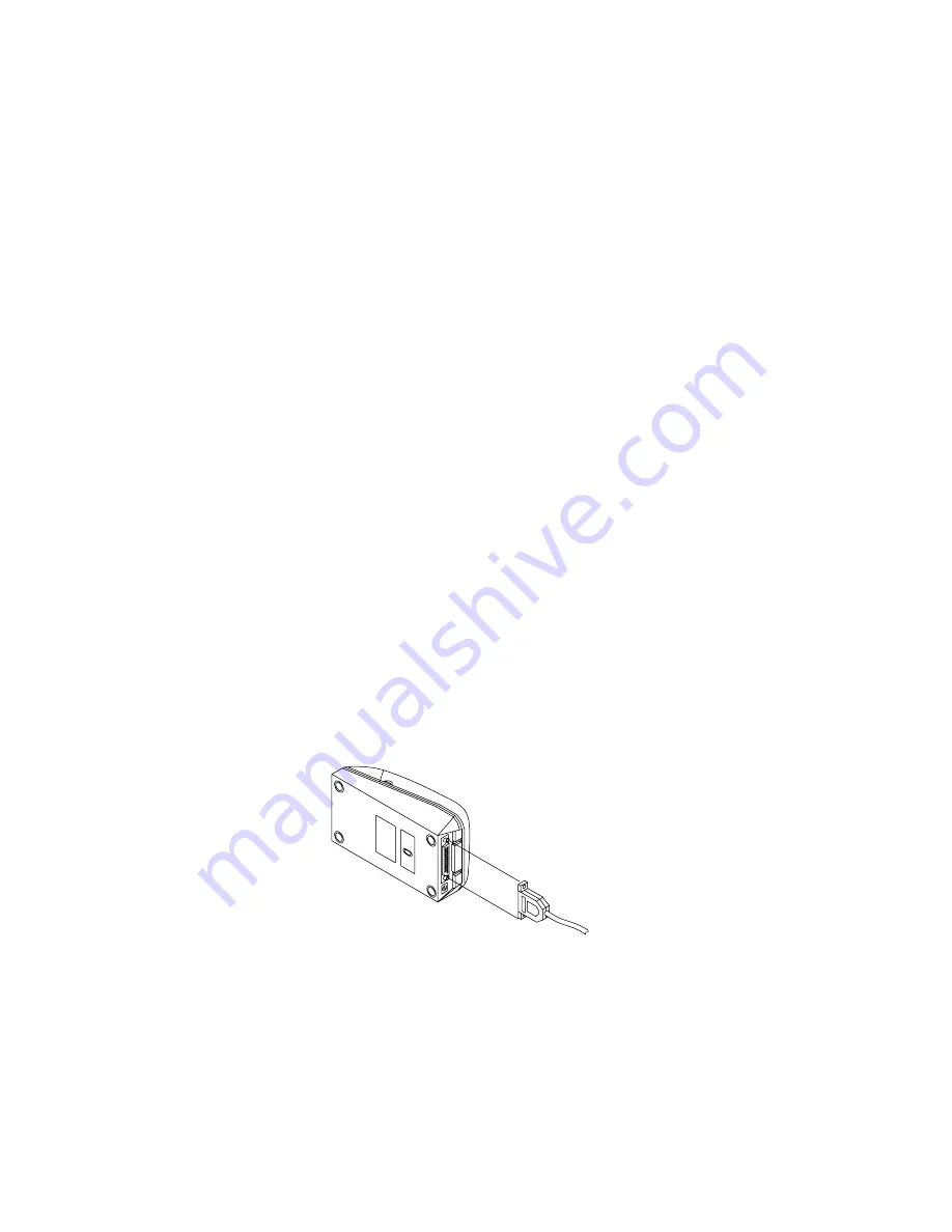
Connecting the Interface Cable

You need an appropriate serial interface or parallel interface cable to connect
your computer to the printer.

3-4-1

Serial Interface Cable: OM19

-S

1. Make sure that both the printer and computer are turned off.
2. The serial printer comes with a DB-25 female connector. Plug the DB-25

male end of the cable into the printer connector, as shown above.

Summary of Contents for intell-print om-192-s

Page 1: ...1 A Higher Level of Precision A Higher Level of Performance Intell Print OM 192 S Dot Matrix Printer User Operation Manual...

Page 2: ...onics parallel x Multiple international character set x Auto power off features x User selectable options stored in non volatile ram x Watch dog software shuts off power to the print head and carriage...

Page 3: ...60 DH1000 Data buffer 1 KB Ink ribbon ERC 09 or ERC 22 Purple or black Paper Width 57 5 r 0 5 mm Diameter 60 mm Max No of copies Original 1 copy Power supply 9 VDC r10 2 0 A Dimensions mm 178 L x 105...

Page 4: ...3 Setting up the printer 3 1 Unpacking The items illustrated below are included with your printer If any items are damaged or missing please contact your dealer for assistance Printer Paper Roll Power...

Page 5: ...the printer 3 Plug the adapter or the power supply s cord into an outlet 4 For best results use one of the following Omniprint adapters OMPS190 915 NA 120VAC input OMPS190 915 EU 220 240VAC input OMPS...

Page 6: ...r to fasten the cable screws to the two nut screws installed on the printer connector 4 Connect the other end DB25 M connector to your computer 5 Use Omniprint part number CBL 625M 25F STR 3 5 Install...

Page 7: ...d paper roll if any and press the FEED button until any excess paper left in the mechanism is out Do not pull the paper out of the printer mechanism paper inlet 3 Mount the paper roll on the paper rol...

Page 8: ...ight into the paper slot 5 Press the FEED button until approximately two inches of paper is fed through the mechanism 6 Tear the excess paper against the serrated edge and close the cover 7 Use the fo...

Page 9: ...power OFF FEED BUTTON When the FEED button is pressed and then released within 0 5 sec the paper feeds only one line When the FEED button is held depressed for more than 0 5 sec the paper feeds conti...

Page 10: ...ILL GO OFF LINE AND WILL NOT COMMUNICATE WITH THE HOST WHILE IT IS IN SELF TEST MODE 7 Default settings Your printer is supplied with the following default setting DATA BITS 8 PARITY NONE BAUD RATE 96...

Page 11: ...selected it can be saved by pressing the SEL button while pressing the FEED button NOTE IF NO BUTTONS ARE PRESSED FOR 15 SECONDS THE SET UP MODE IS AUTOMATICALLY TERMINATED WITHOUT CHANGING THE ORIGI...

Page 12: ...d the printer will print set error nvr unchanged 8 3 NVR COMMS STRING SET UP MODE ODH N1 N2 N3 N4 0 1 2 3 4 5 6 7 8 9 10 1 Data bit 7 8 2 Parity EVEN ODD NONE 3 Baud rate 19200 9600 4800 2400 4 Countr...

Page 13: ...oubleshooting 1 IF THE POWER LED DOES NOT COME ON Make sure the power supply cables are securely plugged into the printer the adapter and the power outlet Also make sure that power is supplied to the...

Page 14: ...n on both ends of the cable between the printer and the host C The data transmission setting may be different between the printer and the host Use the SET UP instructions to change the settings if nec...

Page 15: ...1 DTR 20 OUT Please note that some models can be set at the factory to receive power through the serial port 11 1 3 Serial Interface Timing Diagram 11 2 PARALLEL INTERFACE 11 2 1 Parallel Interface Sp...

Page 16: ...host while the BUSY signal is in the LOW state and communication will be interrupted when the signal is HIGH 12 COMMAND CODES 12 1 COMMAND SUMMARY FOR DH1000 EMULATION FUNCTION KEYSTROKE HEX DECIMAL H...

Page 17: ...AGE LENGTH FORMAT ESC C 1BH 43H PAGING IS OFF ESC 0 1BH 4FH 2 75MM SPACING ESC1 1BH 31H 5 5MM SPACING ESC 2 1BH 32H COMMANDS ACKNOWLEDGED BUT NOT EXECUYED DOUBLE WIDTH 1EH 30 SINGLE WIDTH 1FH 31 11 2...

Page 18: ...nt white on black You can toggle between reverse and normal anywhere on a line but the reverse print mode will automatically be terminated at the end of a line DOUBLE HEIGHT 1AH Upon receiving this co...

Page 19: ...1BH 52H n Selects the international character set form the following table n Character set 0 U S A 1 France 2 Germany 3 U K 4 Denmark I 5 Sweden 6 Italy 7 Spain 8 Japan 9 Norway 10 Denmark II ESC d n...

Page 20: ...UFFER 18H All the data in the print buffer received prior to this command will be cleared however this code is treated as data in the graphics mode DOUBLE WIDTH 1EH Upon receiving this command the pri...

Page 21: ...21 APPENDIX 2 PRINTABLE CHARACTER SET...

Page 22: ...22 APPENDIX 3 EXTERNAL DIMENSIONS...

Page 23: ...23...

Reviews: