Intelligent Home Cat-5 network cable User Manual Download Page 1

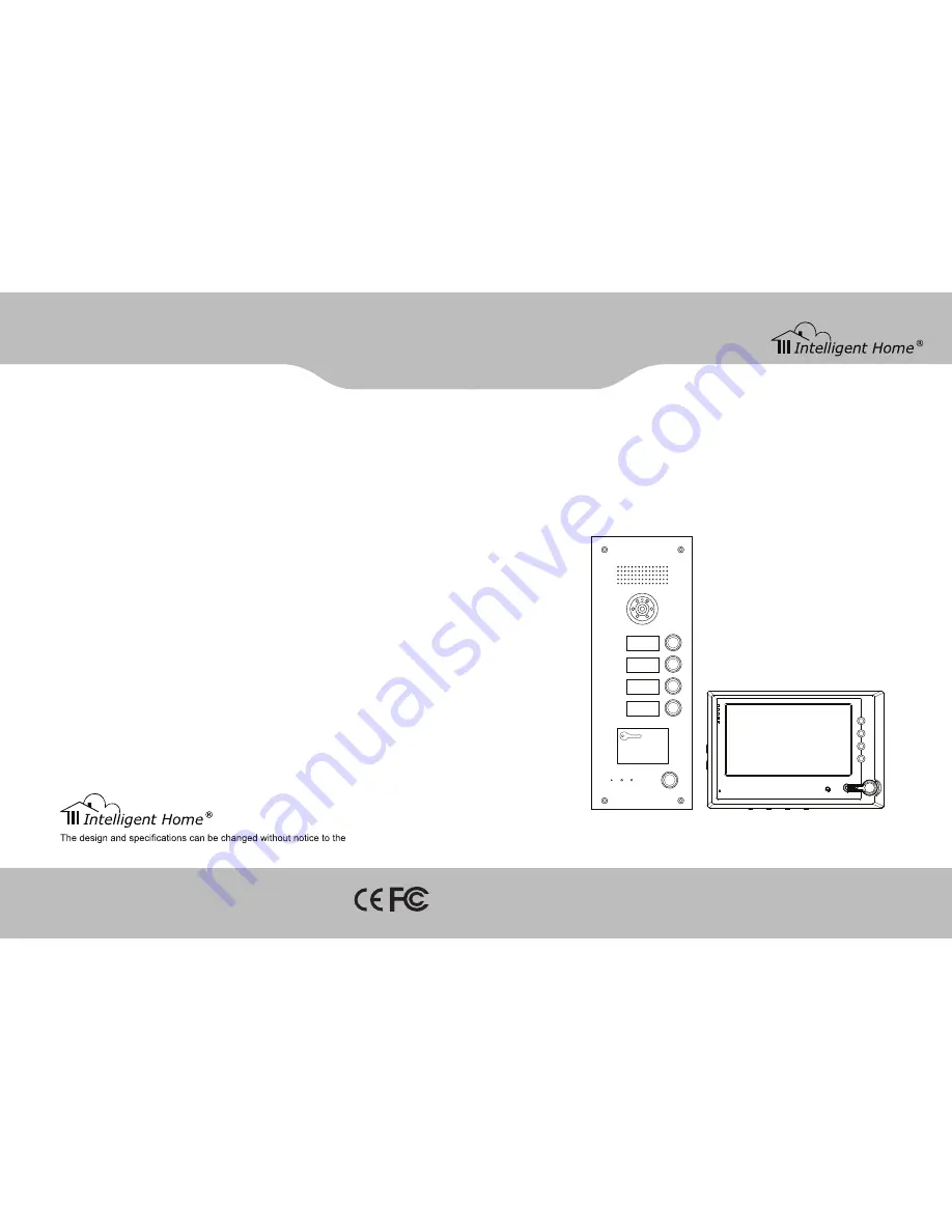
Video Door Entry System

for Flats / Aprtments

user manual

Cat-5 network cable

www.intelligenthomeonline.com

www.intelligenthomeonline.com

user. Right to interpret and copyright of this manual are preserved.

101

201

301

401

10

SPEAK

NOW

DOOR

SERVICE

OPEN

Summary of Contents for Cat-5 network cable

Page 1: ...for Flats Aprtments user manual Cat 5 network cable www intelligenthomeonline com www intelligenthomeonline com user Right to interpret and copyright of this manual are preserved 101 201 301 401 10 SPEAK NOW DOOR SERVICE OPEN ...

Page 2: ...isassembling the device 4 Attempting to force the device to perform functions for which it is not intended 5 Attaching the device to power supplies other than thoserecommended by the manufacturer Distributor for Warranty purposes Lale Trading Ltd 34a High Street Hornsey London N87NX 44 0 20 83482040 www intelligenthomeonline com Product _____________________________________________ Purchaser Name ...

Page 3: ... Connection explanation 6 Switch wiring diagram 7 Gate way wiring diagram 8 Distributor wiring diagram 9 Multiple door stations extension wiring map 10 Door station electric lock wring diagram 11 4 System programming 12 Building programming 12 Network system programming 23 5 Project case 28 Customer requirement description 28 Components 28 System wiring diagram 29 System Programming 30 6 Product i...

Page 4: ...veral ways for door release It can be from indoor phone or guard unit to unlock or by password or IC ID card etc to unlock Alarm Indoor phone can send alarm signal to guard unit Note Below functions only apply to indoor phone with alarm area Alarm message can be sent to guard unit automatically and guard unit can check the alarm types time place and resident information through the remote computer...

Page 5: ...with the intercom door release and other functions Operating voltage DC30 35V Quiescent current 90mA Operating current 260mA Network equipments optional Network switch Achieve the function of switching signal among every branch Operating voltage DC30 35V Quiescent current 180mA Operating current 200mA Network equipment basic Gate way Achieve the function of audio and video signal switch function O...

Page 6: ...rating voltage DC30 35V Quiescent current 15mA Operating current 60mA Unit equipment optional 52 Appendix 4 RJ45 plug making method Firstly introduce some tools and materials needed for making RJ45 plug RJ45 plug CAT 5 Clamp RJ45 plug RJ45 Plug is the connector of CAT 5 with module jack structure There are 8 grooves on the front of the connector called 8P Position and there are 8 metal contact poi...

Page 7: ...03 Current _ _ _ _ New _ _ _ _ Confirm _ _ _ _ Press Confirm System PW Public PW Current New Confirm Successful 23 24 25 26 Change public password In P24 choose Public PW press to confirm LCD shows P27 enter system password to change the public password System Password _ _ _ _ Current _ _ _ _ New _ _ _ _ Confirm _ _ _ _ Press confirm Enter correct system password LCD shows P28 change public passwo...

Page 8: ...fo No 0007234177 Seq No 001 Qty 012 Time setting In P3 choose Time Date press LCD shows P16 set time according to hint press to confirm The system will back to P3 automatically after setting Note When setting press F3 and F4 to move cursor to choose function 07 01 01 00 00 00 Monday 16 Password unlocking In P3 choose PW Unlock press LCD shows P17 set the unlock type after setting press to back to ...

Page 9: ...arm Setting 1 Choose ON 0 Choose OFF Current OFF 6 Alarm setting In P3 select Alarm Setting press to confirm enter P6 according the prompt to set the alarm ON OFF Note Use direction key F1 or F2 to choose function press to back to P3 In P7 choose Register Patrol press LCD shows P10 enter card No according to hint press to confirm after successful registration press to back to P7 Register Patrol No...

Page 10: ...tion Enter System Perimeter Gate Card Register Single Register Patrol Delete Single Delete All Time Date PW Unlock Unlock Time System PW Public PW Operate Guide Version No Change PW Help Menu Bit Card Info Key Function F1 To enter function menu and direction key up 1 9 To enter figures or characters F2 Direction key down Confirm key F3 Direction key left public password unlocking Quit F4 Direction...

Page 11: ...ow as P32 Input 0 lift control function is OFF The LCD will show as P33 Input 1 lift control function is OFF The LCD will show as P34 After finish press button return to P31 Floor Setting In the menu of P31 input 1 The LCD will show as P35 Input the floor number press button to confirm e g Second underground floor input F3 2 as the P36 shows 1 floor input 0 1 as the P37 shows In the menu of P3 inp...

Page 12: ...ck to P3 16 17 18 Card registering In the menu of P3 input 3 The LCD will show as P19 Here proceed IC ID card setting 1 Resister single card In the menu of P19 input 0 The LCD will show as P20 input card No press to confirm or put card on door station s card reader and finish single card registration 19 20 21 22 23 3 Delete single card In the menu of P19 input 3 The LCD will show as P22 Input card...

Page 13: ...e 3 types of rings for chosen otherwise it is always Dingdong ring when choose 1 3 10 11 12 13 15 14 In the menu of P8 input 1 the LCD will show as P12 Start No Input the start indoor phone No e g 0101 End No Input the last indoor phone No e g 0704 Ring Type Input ring number 1 3 e g 1 Password Input resident password e g 1234 After finish the LCD shows as P13 press to back to P8 Note The original...

Page 14: ...here can proceed system functions setting Confirm Quit Restore Default Password Hold button on the door station then connect the power the default password will be restored And the LCD will show the version number of software Note The P1 is for example This door station has series of functions and each function has its own function form 1 2 3 7 4 5 6 Door station setting In the menu of P3 input 0 ...

Page 15: ...e distributor number which connect to the same gate way should not be repeat 3 Please take record of the gate way number and distributor number these information may be used in the coming setting Address gate way Set gate way number 1 DIP switch it is in the cover plate on the left side of gate way show as below 2 Address range 001 063 3 Address calculating According to the form below plus all the...

Page 16: ...ge system password In P43 choose System PW LCD shows P44 change system password according to hint e g After input password press if password is correct LCD shows P45 press to back to P43 Note For the first time change the initial password is 2003 Current _ _ _ _ New _ _ _ _ Confirm _ _ _ _ Press Confirm System PW Private PW Public PW Change resident password In P43 choose Private PW press LCD show...

Page 17: ...ding to hint press to confirm 简体中文 English 37 Lift setting In P3 press F1 or F2 to select Lift setting as P38 shows Press to confirm LCD shows P39 1 Lift In P39 press F1 or F2 to select Lift press to confirm LCD shows P40 Set lift ON OFF according to hint 2 Floor Setting In P39 press F1 or F2 to select Floor Setting press to confirm LCD shows P41 Input the start floor number press to confirm Lift ...

Page 18: ...turn to P3 after finish Door station No 0006 Gate Way Port 6 9 40 In P21 choose Register Single LCD shows P23 according to hint input card No press to confirm or put card on door station s sensor and finish single card registration After successful registration shows P24 then input another card s No or put that card on sensor to begin new registration or press to return to P22 Note The card digits...

Page 19: ...0 Indoorphone 2004 Distributor020 4 Ring Type 2 18 Upload Download Clear Gate way 17 Alarm Setting 1 Choose ON 0 Choose OFF Current OFF 21 Alarm setting In P3 select Alarm Setting press to confirm enter P21 according the prompt to set the alarm ON OFF Note Use direction key F1 or F2 to choose function press to back to P3 16 III Matrix input mode Note This mode is only suitable for buildings with m...

Page 20: ...of di can be heard and LCD shows P9 Press button to return to P3 Indoor phone setting In P3 select Indoor Phone press to confirm enter P10 setting each indoor phone functions Note Use direction key F1 or F2 to choose function press to back to P3 10 1 Indoor phone digit In P10 select Bit press to confirm LCD shows P11 choose indoor phone bit according to room No press to confirm after setting the s...

Page 21: ... Data Successful 6 Upload Download Clear Gate way Successful 7 LCD shows P5 according to hint press to cancel all indoor phone No After successful clearance a long sound of di can be heard at the same time LCD shows P6 press to back to last menu P4 This function is used in the first time setting only 2 Cancel gate way data In P4 press F2 to select Clear Gate way press to confirm after gate way dat...

Page 22: ...ws as P10 input next indoor phone No or press to back to P7 Note 1 Ringing is only heard when indoor phone is called 2 When system s ring is chord melody type there are 3 types of rings for chosen If the door station is Dingdong ring type it is always Dingdong ring when choose 1 3 9 10 III Matrix input mode Note This mode is only suitable for buildings with matrix structure if every floor has diff...

Page 23: ...cho ringing guard unit rings when pick up the handset of guard unit guard unit shows it is in conversation but no voice and image A Check if gate way port set on door station is correct or not B Check if the wiring through gate way is right or not C Check if the setting on switch is in accordance with reality the switch indicator light can be for your reference Guard unit has abnormal alarming Che...

Page 24: ... Single columns buttons 3 Unlock time setting 5 sec 1 sec PORT Door station 2 Two columns buttons Three columns buttons Four columns buttons 34 Switch power distributor gate way installation Product name Switch power Distributor Gate way Dimension Method 1 According to hole distance on dimension map install directly onto the wall Method 2 Put the upper buckle on the back of these parts into the U ...

Page 25: ... must enter the system setting 1 Press FN password 4 bits ENTER 2 The door station will sound a long beep and the DOOROPEN LED will flash slowly It means enter the system setting Note the original password is 1234 1 Memory Information clearance Only used in the first time programming 1 Press FN DEL ENTER 2 The door station will sound a long beep And the DOOR OPEN LED will start to flash slowly It ...

Page 26: ...tomatically choose perimeter gate station No and press to confirm Perimeter Gate Card Time Date PW Unlock 1 2 3 LCD shows P4 enter here the perimeter gate station No and switch port No then press to back to P3 Note The valid scope for perimeter gate station is 00 09 Perimeter Gate Switch Port 4 e g Input the data according to left Picture and press to confirm after successful registration shows P5...

Page 27: ... add and press confirm key LCD shows P10 1 Type Door 2 No 0001 3 SwitchPort 00 4 Dist 0 m 10 2 Setting guard unit No Note If there is only one guard unit in network then the guard unit number is 1 According to hint input new guard unit No press confirm key LCD shows P8 then back to P2 Guard No 1 New 2 Save OK 8 3 Add setting form In P10 press down key to check each setting information then it come...

Page 28: ...k to P9 18 30 System Programming Unit door station programming First program first building Step 1 Hardware setting 1 Set DIP of 4300 gate way to 001 as below 2 Set the DIP digit for distributors 4110 4110S in the unit respectively from 001 005 001 002 003 004 005 Step 2 Door station setting first set on main door station 1 Clear data 2 Door station No setting shows as below 3 Indoor phone informa...

Page 29: ...ard unit and gate way port is on or off If the indicator light is on but it is not the same as the real wiring port check the setup form of door station and guard unit check whether they are in accordance with the actual wiring or not Malfunction 5 The door station no shows on the guard unit is not the same with reality Check whether the door station setup form is in accordance with the actual wir...

Page 30: ...not 4 Perimeter gate station calling indoor phone Dial room No on perimeter gate station and call indoor phone indoor phone answers and unlock the door 28 5 Project case Customer requirement description 1 There is a community with two buildings each building has 8 floors from 1 st to 7 th floor there are 2 residents in each floor and in 8 th floor there s only 1 resident 2 There are two door stati...

Reviews: