background image


46

Intel

® 

Server System SR1695GPRX Service Guide

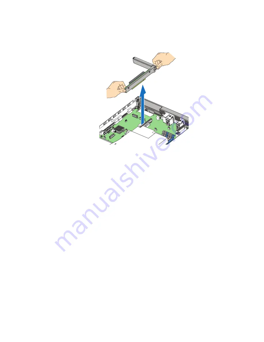
Figure 29. Removing Riser Assembly

8. Install the replacement riser card, if desired.

9. Install the PCIe* Riser assembly into the server system.

10. Install the server system cover. For instructions, see 

“Installing the Server System 

Cover”

.

11. Plug all peripheral devices and the AC power cable into the server.

Installing a PCIe* Riser Card

1. Observe the safety and ESD precautions at the beginning of this book. See 

“Safety 

Information”

.

2. Power down the server and unplug all peripheral devices and the AC power cable.

3. Remove the server system cover. For instructions, see 

“Removing the Server 

System Cover”

.

4. Disconnect any cables attached to any add-in cards.

5. Remove the PCIe* Riser assembly.

6. Remove any add-in cards from the PCIe* Riser connector. For instructions, see 

“Removing a PCI Add-in Card”

.

7. Use the screw to attach the riser card to the riser assembly.

EP0001

Summary of Contents for SR1695GPRX

Page 1: ...Intel Server System SR1695GPRX Service Guide A Guide for Technically Qualified Assemblers of Intel Identified Subassemblies Products Intel Order Number G11460 003...

Page 2: ...r Intel may make changes to specifications and product descriptions at any time without notice Intel server boards contain a number of high density VLSI and power delivery components that need adequat...

Page 3: ...en auf der Intel Server Deployment Toolkit CD oder unter http www intel com support motherboards server sb cs 010770 htm Consignes de s curit Lisez attention toutes les consignes de s curit et les mis...

Page 4: ...iv Intel Server System SR1695GPRX Service Guide...

Page 5: ...amage can result Electrostatic discharge ESD and ESD protection ESD can damage disk drives boards and other parts We recommend that you perform all procedures in this chapter only at an ESD workstatio...

Page 6: ...vi Intel Server System SR1695GPRX Service Guide...

Page 7: ...rams to help you identify components and their locations Chapter 2 provides instructions on using the utilities shipped with the board or that may be required to update the system This includes how to...

Page 8: ...ribution Board inside System fan assembly including two blowers and one rotor Chassis rack handles Four HDD carriers supporting four hot swap 3 5 or 2 5 SATA SAS HDDs One passive processor heatsinks O...

Page 9: ...his is available from your Intel field representative or on the Server Configurator Tool at http www intel com p en_US support highlights server s3420gp Hardware peripheral boards adapter cards and op...

Page 10: ...em SR1695GPRX Service Guide For diagnostics test software Diagnostics http www intel com p en_US support highlights server s3420gp Server System References For this Information or Software Use this Do...

Page 11: ...1 Chassis Component Identification 4 System Front Panel SR1695GPRX 4 System Rear 8 Peripheral Devices SR1695GPRX 10 Hard Disk Drives 10 Slimline Optical Drive Carrier 11 Internal Components SR1695GPR...

Page 12: ...swap Hard Drive 39 Installing a SAS or SATA Hot swap Hard Disk Drive 39 Removing a SAS or SATA Hot swap Hard Disk Drive 42 Installing or Removing a Slimline Optical Drive SR1695GPRX 42 Installing a S...

Page 13: ...ems following Initial System Installation 74 First Steps Checklist 74 Hardware Diagnostic Testing 74 Verifying Proper Operation of Key System Lights 75 Confirming Loading of the Operating System 75 Sp...

Page 14: ...er ten 101 Warnungen zu Netzspannung und Elektrizit t 102 Warnhinweise f r den Systemzugang 102 Elektrostatische Entladungen ESD 103 Andere Gefahren 104 Fran ais 105 Consignes de s curit sur le serveu...

Page 15: ...mpliance Markings 125 Electromagnetic Compatibility Notices 131 FCC Verification Statement USA 131 Industry Canada ICES 003 132 Europe CE Declaration of Conformity 132 VCCI Japan 132 BSMI Taiwan 133 K...

Page 16: ...xviii Intel Server System SR1695GPRX Service Guide...

Page 17: ...0 Removing the Protective Socket Cover 37 Figure 21 Installing the Heat Sink 38 Figure 22 Pulling out the back lever 39 Figure 23 2 5 HDD Installation 40 Figure 24 3 5 HDD Installation 41 Figure 25 Lo...

Page 18: ...m SR1695GPRX 63 Figure 45 Installing Fan into the Server System SR1695GPRX 64 Figure 46 Replacing the Rotor Fan 65 Figure 47 Installing the Rack Handle 66 Figure 48 Removing the Rack Handle 66 Figure...

Page 19: ...LED Operation 5 Table 5 System Status LED Operation 6 Table 6 NIC LED Descriptions 8 Table 7 Channel Slot Configuration 16 Table 8 Setup Menu Key Use 20 Table 9 Power Supply Output Capability 71 Tabl...

Page 20: ...xxii Intel Server System SR1695GPRX Service Guide...

Page 21: ...er briefly describes the main features of the server system This chapter provides illustrations of the product a list of the server system features and diagrams showing the location of important compo...

Page 22: ...n socket Support for one Intel CoreTM i3 Processor 2 0 GT s point to point DMI interface to PCH LGA 1156 pin socket Memory Two memory channels with support for 1066 1333 MHz Unbuffered UDIMM or ECC Re...

Page 23: ...tel SAS Entry RAID Module AXX4SASMOD provides entry level hardware RAID 0 1 10 and native SAS pass through mode 4 ports full featured SAS SATA hardware RAID through optional Intel Integrated RAID Modu...

Page 24: ...m Front Panel SR1695GPRX The front of the server system includes the following buttons and LEDs Figure 2 Front Controls and LEDs SR1695GPRX Table 2 Front Control Button Function A Power Sleep Button B...

Page 25: ...5 state LAN Green On LAN Link no Access Green Blink LAN Activity Off No link System Status Green On System Ready No Alarm Green Blink System ready but degraded redundancy lost such as the power supply...

Page 26: ...Ok System ready Blink Degraded BIOS detected 1 Unable to use all of the installed memory more than one DIMM installed 1 2 In a mirrored configuration when memory mirroring takes place and system lose...

Page 27: ...o fail BIOS detected 1 In non mirroring mode if the threshold of ten correctable errors is crossed within the window 1 2 PCI Express uncorrectable link errors Integrated BMC Detected 1 Critical thresh...

Page 28: ...ndant Power Supply Units G RJ 45 Serial Port B Power Supply Status LED H PCI Express Add in slot C NIC 1 2 connectors RJ 45 I Reserved for IO module external connectors D Video Out J Top cover lock sc...

Page 29: ...SR1695GPRX Service Guide 9 B N A Off 10 Mbit sec data rate is selected Green On 100 Mbit sec data is selected Yellow On 1000 Mbit sec data rate is selected Table 6 NIC LED Descriptions LED LED State...

Page 30: ...Intel Server System SR1695GPRX ships with four hot swap drive carriers for installing four SATA SAS hard disk drives either 3 5 inch or 2 5 inch HDDs For instructions on installing hard drives see Ins...

Page 31: ...bay is NOT hot swappable To use one of the drives provided by Intel use the following order codes SATA slimline DVD drive AXXSATADVDROM SATA slimline DVD rewritable drive AXXSATADVDRWROM Note The Inte...

Page 32: ...1695GPRX Figure 4 System Components SR1695GPRX EP0003 A B C D E G H I J F K A Server Board G System Blowers 2 B Power Supply H Front Panel C Hard Drive Bays I Rotor Fan D Slimline Optical Drive Bay J...

Page 33: ...Intel Server System SR1695GPRX Service Guide 13 Server Board Connectors Components...

Page 34: ...B Connector F Dual port RJ 45 GbE LAN Connector NIC3 and NIC4 Y SATA SGPIO Connector G SATA RAID key Z HSBP Connector H DB15 Video port AA USB Floppy I Dual port RJ 45 GbE LAN Connector NIC1 and NIC2...

Page 35: ...mpatible server cabinet A tool less slide rail kit Product order code AXXHERAIL2 is designed to mount the chassis into a standard 19 inches by up to 30 inches deep EIA 310D compatible server cabinet A...

Page 36: ...lso support Intel CoreTM i3 processor For a complete list of supported processors see the links under Server System References Memory The Intel Server Board S3420GPRX supports a DDR3 based memory sub...

Page 37: ...opulated in any order and have no matching requirements All channels must run at the same interface frequency but individual channels may run at different DIMM timings RAS latency CAS latency etc The...

Page 38: ...18 Intel Server System SR1695GPRX Service Guide...

Page 39: ...d previously during the Power On Self Test POST you will see this prompt Press F2 to enter SETUP In a third condition when CMOS NVRAM is corrupted you will see other prompts but not the F2 prompt Warn...

Page 40: ...he associated pick list without displaying the full list On 106 key Japanese keyboards the plus key has a different scan code than the plus key on the other keyboard but it has the same effect Enter E...

Page 41: ...recovery process to return the system to service See Server System References for a link to necessary software and instructions Recording the Current BIOS Settings 1 Boot the computer and press F2 wh...

Page 42: ...e your settings and exit Setup Recovering the BIOS If an update to the system BIOS is not successful or if the system fails to complete POST and the BIOS is unable to boot an operating system it may b...

Page 43: ...g the progress and the system will automatically boot to the EFI SHELL 6 Remove the recovery media 7 Power down and unplug the system from the AC power source 8 Move the BIOS recovery jumper at J1F3 b...

Page 44: ...sword Clear Protect position covering pins 1 and 2 7 Reconnect the AC power and power up the server 8 Close the server chassis The password is cleared and can be reset by going into the BIOS setup Cle...

Page 45: ...up Updating the Integrated BMC Figure 10 BMC Force Update Jumper When performing the standard Integrated BMC firmware update procedure the update utility places the Integrated BMC into an update mode...

Page 46: ...er down and remove the AC power cord 2 Open the server chassis For instructions refer to your server chassis documentation 3 Move the jumper from the default operating position covering pins 1 and 2 t...

Page 47: ...by pressing the power button and unplug the AC power cord from the system or wall outlet Note Most of the illustrations in this chapter show the Intel Server System SR1695GPRX with an optional optica...

Page 48: ...ove the server system cover power down the server and unplug all peripheral devices and the power cable Note You may need a non skid surface or a stop behind the server system to prevent the server sy...

Page 49: ...r system sidewalls Slide the cover forward see letter A in Figure 12 3 Tighten the screw at the rear of the server see letter B and install the top cover screw see letter C Figure 12 Installing the Se...

Page 50: ...the beginning of this book See Safety Information 2 Power down the server and unplug all peripheral devices and the power cable 3 Remove the server system cover For instructions see Removing the Serve...

Page 51: ...ables that may be near or under the air duct 5 Install the server system cover For instructions see Installing the Server System Cover Figure 14 Installing the Processor Air Duct Installing and Removi...

Page 52: ...tter A in Figure 15 6 Holding the DIMM by the edges remove it from its anti static package 7 Position the DIMM above the socket Align the notch on the bottom edge of the DIMM with the key in the DIMM...

Page 53: ...nstructions see Removing the Server System Cover 4 Locate the DIMM sockets See Figure 15 5 Gently spread the retaining clips at each end of the socket The DIMM lifts from the socket 6 Holding the DIMM...

Page 54: ...round unnecessarily Removing the Heat Sink and Processor 1 Observe the safety and ESD precautions at the beginning of this book See Safety Information 2 Power down the server and unplug all peripheral...

Page 55: ...unplug all peripheral devices and the AC power cable 3 Remove the server system cover For instructions see Removing the Server System Cover 4 Locate the processor socket and raise the socket handle c...

Page 56: ...Load Plate Caution Do not touch the socket pins they are very sensitive and easily damaged 6 Remove the processor from the packaging box and remove the protective shipping cover See Figure 18 Figure...

Page 57: ...ace as shown by letter B in Figure 19 Figure 19 Installing the Processor Note Make sure the alignment triangle mark and the alignment triangle cutout align correctly 9 Remove the protective socket cov...

Page 58: ...AIRFLOW AF003369 1 Remove the protective cover from the TIM on the underside of the heat sink Do not touch the TIM 2 Orient the heat sink over the processor as shown in Figure 21 You must position th...

Page 59: ...by carriers with drive blanks to maintain proper system cooling To avoid possible damage to your server system use only the drive carriers that came with your system Installing a SAS or SATA Hot swap...

Page 60: ...position the connector end of the drive so that it is facing the rear of the drive carrier 6 Align the holes in the drive to the holes in the drive carrier and attach it to the carrier with the screws...

Page 61: ...nto the server system The green latch at the front of the drive carrier must be to the right Do not push on the black drive carrier lever until the lever begins to close by itself 8 When the black dri...

Page 62: ...ive carriers must be installed in the server system and populated either with a drive or without a drive to maintain system thermals 4 When the black lever begins to close by itself push on it to lock...

Page 63: ...tain the optical drive and the optical drive latch from system package 3 Screw the latch to the optical drive and plug in the composed SATA SATA Power cable which is shipped in system package Figure 2...

Page 64: ...A in the following figure The assembly will automatically be locked if the drive assembly is in position 6 Connect the SATA cable connector to SATA port 4 or 5 on server board 7 Connect the SATA power...

Page 65: ...lot Note To eliminate the possibility of installing the replacement connector on the wrong side of the PCIe Riser assembly replace one connector at a time Replacing a PCIe Riser Card 1 Observe the saf...

Page 66: ...nstalling a PCIe Riser Card 1 Observe the safety and ESD precautions at the beginning of this book See Safety Information 2 Power down the server and unplug all peripheral devices and the AC power cab...

Page 67: ...Air Duct 12 Install the server system cover For instructions see Installing the Server System Cover 13 Plug all peripheral devices and the AC power cable into the server Installing and Removing a PCI...

Page 68: ...ly until it seats in the riser card connector but use caution so you do not twist or bend the card See letter C in Figure 31 8 Re install the screw you removed in Step 5 See letter A in Figure 31 Figu...

Page 69: ...bly See letter C in Figure 32 8 Re install the screw you removed in Step 5 See letter A in Figure 32 Figure 32 Removing a Full Height Add In Card Note Make sure that all empty add in card slots have f...

Page 70: ...of the I O expansion module cover to disengage it from the server system back panel and remove it see letter A Figure 33 Installing the I O Expansion Module s 2 Attach the standoffs to the server boar...

Page 71: ...xpansion Module s Removing the I O Expansion Module s 1 Remove the I O expansion module s from the server board see letter A 2 Remove the standoffs from the server board see letter B 3 Install the I O...

Page 72: ...M3 Lite over the server board RMM3 Lite connector J2D1 as shown in Figure 35 Figure 35 Installing the RMM3 Lite to the Server System 3 Install the PCI riser assembly into the server system For instruc...

Page 73: ...lling a PCIe Riser Card Replacing the Backplane Board The instructions below describe how to replace the backplane board in the system Removing the Backplane Board 1 Disengage hard drives from the bac...

Page 74: ...lane assembly into the system see letter A and fix the backplane assembly into fix position aligning with two screw holes on chassis 2 Tighten two screws to lock the backplane assembly in position see...

Page 75: ...Intel Server System SR1695GPRX Service Guide 55 Figure 38 Installing the backplane board EP0015 A B C...

Page 76: ...embly 4 If installed disconnect all SATA cables from the server board 5 Disconnect the system fans cables from server board 6 Disconnect all power cables coming from the power supply to the server boa...

Page 77: ...ch the server board with nine screws see letter B Figure 40 Installing the Server Board 3 Re connect all power cables coming from the power supply to the server board 4 Re connect the system fan cable...

Page 78: ...umbatteri Eksplosionsfare ved fejlagtig h ndtering Udskiftning m kun ske med batteri af samme fabrikat og type Lev r det brugte batteri tilbage til leverand ren Advarsel Lithiumbatteri Eksplosjonsfare...

Page 79: ...7 Dispose of the battery according to local ordinance 8 Remove the new lithium battery from its package and being careful to observe the correct polarity insert it in the battery socket 9 Close the c...

Page 80: ...it fails or if one of the fans integrated into it fails To replace the power supply use the following instructions 1 Disconnect the power cord see letter A 2 Hold the handle and press the latch see l...

Page 81: ...ng the Power Supply 1 Insert the replacement power supply module into the power supply cage and push hard until it clicks into place see letter A 2 Connect the power cord see letter B Figure 43 Instal...

Page 82: ...ly replace them If a fan in the power supply fails you must replace the power supply Use the following steps to replace a system blower fan or the PCI cooling fan Replacing the System Blower Fans SR16...

Page 83: ...Removing Fan from the Server System SR1695GPRX 8 Install the replacement fan into the chassis see letter A in Figure 45 using the two screws you removed previously 9 Connect the fan cable to the serve...

Page 84: ...the safety and ESD precautions at the beginning of this book See Safety Information 2 Power down the server and unplug all peripheral devices and the AC power cable 3 Remove the server system cover Fo...

Page 85: ...EP0018 EP0026 Intel Server System SR1695GPRX Service Guide 65 Figure 46 Replacing the Rotor Fan...

Page 86: ...e holes on the side of the server system and attach the rack handle with the three screws Figure 47 Installing the Rack Handle 2 Repeat step 1 on the opposite side of the server Removing the Rack Hand...

Page 87: ...front bezel is available as an optional accessory for the Intel Server System SR1695GPRX A B AF003544 W i l l o w B r o o k O p t i c a l D e v i c e AF003541 Removing the Front Bezel 1 Unlock the bez...

Page 88: ...X Service Guide Installing the Front Bezel 1 At each end of the bezel line up the center notch on the bezel with the center guide on the rack handles and push the bezel onto the front of the server sy...

Page 89: ...locked Use the following figures to determine the correct cable routing For readability separate figures for power cable routing and data cable routing are included Make sure all necessary power and d...

Page 90: ...ide Cable Routing SR1695GPRX Figure 51 Cable Routing SR1695GPRX B a t t e r y B a c k u p U n i t Power Supply BBU Optical Drive EP0020 RAID Card Server Board Front Panel HDD 0 HDD 1 HDD2 HDD3 Front P...

Page 91: ...400 W Single Power Supply Output Voltages Table 9 lists the total wattage available from the power subsystem for each voltage For information about calculating the power usage for your configuration...

Page 92: ...office ambient temperature 23 C 2 C Sound Power 7 0 BA in an idle state at typical office ambient temperature 23 2 degrees C Shock operating Half sine 2 g peak 11 mSec Shock unpackaged Trapezoidal 25...

Page 93: ...he Platform Confidence Test that may help with your diagnostics See Server System References for a link to this software If you cannot resolve your server problems on your own see Getting Help for ass...

Page 94: ...d peripheral devices correct To check these settings refer to the manufacturer s documentation that comes with them If applicable ensure there are no conflicts for example two add in boards sharing th...

Page 95: ...he power LED does light attempt to boot from a USB floppy or from a CD ROM disk 6 Turn on the system If the power LED does not light see Power Light Does Not Light Verifying Proper Operation of Key Sy...

Page 96: ...ke sure the memory DIMMs have been populated according to the system requirements Remove the memory DIMMs and re seat them Make sure the processor s comply with the system requirements Make sure the p...

Page 97: ...cters on the screen after you reboot the system and POST emits a beep code write down the beep code you hear This information is useful for your service representative 5 If you do not receive a beep c...

Page 98: ...he drive properly configured Is the drive activity light always on If so the signal cable may be plugged in incorrectly CD ROM Drive or DVD ROM Drive Activity Light Does Not Light Check the following...

Page 99: ...is current See Server System References for a link to the current version Make sure the other adapter supports shared interrupts Make sure your operating system supports shared interrupts Try reseati...

Page 100: ...orrectly sometimes indicate equipment failure However they can also be caused by file corruption or changes to the software configuration Check the following If you are running the software from a CD...

Page 101: ...e See Server System References for a link to the tested drives Make sure you have not exceeded the power budget for the server See Server System References for a link to software to check your power b...

Page 102: ...82 Intel Server System SR1695GPRX Service Guide...

Page 103: ...s is considered the disconnect device to the main AC power The socket outlet that the system plugs into shall be installed near the equipment and shall be easily accessible SAFETY STEPS Whenever you...

Page 104: ...the system 2 Check that cables add in boards and other components are properly installed 3 Attach the covers to the chassis with the screws removed earlier and tighten them firmly 4 Insert and lock th...

Page 105: ...ded with a properly grounded wall outlet Provided with sufficient space to access the power supply cord s because they serve as the product s main power disconnect Benutzer k nnen am Netzger t dieses...

Page 106: ...Stromanschlu stecker Ihres Systems aus der Steckdose 4 Auf der R ckseite des Systems beschriften und ziehen Sie alle Anschlu kabel von den I O Anschl ssen oder Ports ab 5 Tragen Sie ein geerdetes Anti...

Page 107: ...uber und staubfrei sein Hausstaub ausgenommen gut gel ftet und keinen Heizquellen ausgesetzt sein einschlie lich direkter Sonneneinstrahlung keinen Ersch tterungen ausgesetzt sein keine starken von el...

Page 108: ...u syst me 2 Mettez le syst me hors tension en mettant l interrupteur g n ral en position OFF bouton poussoir 3 D branchez tous les cordons d alimentation c a du syst me et des prises murales 4 Identif...

Page 109: ...ux broches aigu s des cartes et aux bords tranchants du capot Nous vous recommandons l usage de gants de protection Danger d explosion si la batterie n est pas remont e correctement Remplacer uniqueme...

Page 110: ...r desenchufar todos los cables de corriente alterna de la pared o desconectar la fuente de alimentaci n INSTRUCCIONES DE SEGURIDAD Cuando extraiga la tapa del chasis para acceder al interior del siste...

Page 111: ...ables las placas adicionales y otros componentes se hayan instalado correctamente 3 Incorpore las tapas al chasis mediante los tornillos extra dos anteriormente tens ndolos firmemente 4 Inserte el blo...

Page 112: ...tes de vibraci n Aislado de campos electromagn ticos fuertes producidos por dispositivos el ctricos En regiones con frecuentes tormentas el ctricas se recomienda conectar su sistema a un eliminador de...

Page 113: ...re all interno del sistema seguire i seguenti passi 1 Spegnere tutti i dispositivi periferici collegati al sistema 2 Spegnere il sistema usando il pulsante spento acceso dell interruttore del sistema...

Page 114: ...ti Fare attenzione alla presenza di piedini appuntiti e parti taglienti sulle schede e sul telaio consigliabile l uso di guanti di protezione Esiste il pericolo di un esplosione se la pila non viene s...

Page 115: ...product certifications and approvals Use only the described regulated components specified in this guide Use of other products components will void the UL Listing and other regulatory approvals of th...

Page 116: ...entilated and away from sources of heat including direct sunlight and radiators Away from sources of vibration or physical shock Isolated from strong electromagnetic fields produced by electrical devi...

Page 117: ...Pole Fusing To avoid risk of shock use caution when working with power supplies that use Neutral Pole Fusing The power supply in this product contains no user serviceable parts Do not open the power...

Page 118: ...in place Electrostatic Discharge ESD Caution ESD can damage disk drives boards and other parts We recommend that you perform all procedures at an ESD workstation If one is not available provide some...

Page 119: ...rte Peripherieger te Es enth lt Warnungen und Vorsichtsma nahmen zur Vermeidung von Gefahren durch Verletzung Stromschlag Feuer und Besch digungen von Ger ten Lesen Sie diese Dokument daher sorgf ltig...

Page 120: ...bereiche als IT z B Medizin Industrie Alarmsysteme oder Pr fger te kann u U weitere Tests erfordern VORSICHT Weist auf eine Gefahrenquelle hin die bei Nichtbeachtung des VORSICHTSHINWEISES zu leichter...

Page 121: ...ystem an einen berspannungsschutz anschlie en und bei einem Gewitter die Telekommunikationskabel zum Modem abziehen Eine ordnungsgem geerdete Wandsteckdose mu vorhanden sein Ausreichender Freiraum f r...

Page 122: ...bestehen gef hrliche Spannungen Str me und Energiequellen Schicken Sie das Ger t f r Wartungsarbeiten an den Hersteller zur ck Wenn Sie ein hot plug f higes Netzteil austauschen ziehen Sie dessen Net...

Page 123: ...eben werden Elektrostatische Entladungen ESD Vorsicht Elektrostatische Entladungen k nnen zur Besch digung von Festplatten Platinen und anderen Komponenten f hren Daher sollten Sie alle Arbeiten an ei...

Page 124: ...em nur mit angebrachten Geh useabdeckungen betrieben werden Die Inbetriebnahme des Systems ohne Abdeckung kann zur Besch digung von Systemkomponenten f hren So bringen Sie die Abdeckung wieder an Verg...

Page 125: ...fications et approbations de produit existantes Utilisez uniquement les composants d crits et r glement s sp cifi s dans ce guide L utilisation d autres produits composants annulera la liste UL et les...

Page 126: ...ssi re normale d une pi ce Bien ventil et l cart des sources de chaleur telles que la lumi re directe du soleil et les radiateurs l cart des sources de vibration ou des chocs physiques Isol des champs...

Page 127: ...e manipulation de l quipement R duisez le risque de dommages personnels ou mat riels Conformez vous aux exigences de m decine du travail et de s curit lorsque vous d placez et soulevez le mat riel Uti...

Page 128: ...chaud d branchez le cordon du bloc d alimentation en cours de remplacement avant de le retirer du serveur Pour viter tout risque d lectrocution mettez le syst me hors tension et d branchez les cordon...

Page 129: ...non peinte de votre serveur lorsque que vous manipulez les pi ces Manipulez toujours les cartes avec pr caution Elles peuvent tre extr mement sensibles aux ESD Ne tenez les cartes que par leurs bords...

Page 130: ...l En el caso de que haya diferencias entre la informaci n para un producto en particular contenida en este documento y la informaci n proporcionada con dicho producto o en el sitio Web la documentaci...

Page 131: ...Indica la existencia de un riesgo que podr a causar lesiones personales o da os en la propiedad leves si no se tiene en cuenta la PRECAUCI N ADVERTENCIA Indica la existencia de un riesgo que podr a ca...

Page 132: ...ersonales o en el equipo Respete los requisitos de sanidad y seguridad laborales de su pa s cuando traslade y levante el equipo Utilice medios mec nicos u otros que sean adecuados al trasladar o levan...

Page 133: ...onectados a este producto Pulse el bot n de alimentaci n para apagar el sistema Desconecte la alimentaci n de CA desenchufando los cables de alimentaci n de CA del sistema o de la toma de corriente al...

Page 134: ...otecci n o del servidor col quela con el lado de los componentes hacia arriba sobre una superficie con toma de tierra y sin carga est tica Utilice una almohadilla de espuma conductora si dispone de el...

Page 135: ...iones del producto Perif ricos o dispositivos l ser Precauci n Para evitar el riesgo de la exposici n a radiaciones o de da os personales No abra la caja de ning n perif rico o dispositivo l ser Los p...

Page 136: ...116 Intel Server System SR1695GPRX Service Guide Intel Intel Intel Web UL...

Page 137: ...Intel Server System SR1695GPRX Service Guide 117 ITE ITE 5V...

Page 138: ...118 Intel Server System SR1695GPRX Service Guide...

Page 139: ...Intel Server System SR1695GPRX Service Guide 119 ESD ESD ESD ESD ESD...

Page 140: ...120 Intel Server System SR1695GPRX Service Guide...

Page 141: ...r more information please contact your local Intel representative This is an FCC Class A device Integration of it into a Class B system does not result in a Class B device Product Safety Compliance Th...

Page 142: ...e following electromagnetic compatibility EMC regulations when installed in a compatible Intel host system For information on compatible host system s refer to Intel s Server Builder Web site or conta...

Page 143: ...PPM for Cadmium China RoHS MII Measure 39 Product marked with the Environmental Friendly Usage Period EFUP label of 20yrs substance table in Simplified Chinese either placed with the product documenta...

Page 144: ...e on fan Current Limiting Devices Used for Safety for example fuse PTC Minimum Certifications UL and TUV or VDE Lithium Batteries UL recognized and battery circuits are to have suitable reverse bias c...

Page 145: ...labels may be printed from a UL approved label printing system and suitable for the surface it is being applied to Certifications Registrations Declarations UL Certification US Canada GS Certificatio...

Page 146: ...duct Regulatory Compliance Markings Regulatory Compliance Region Marking IRAM Mark Argentina Ctick Mark Australia NZ N232 EMC Marking Canada CANADA ICES 003 CLASS A CE Mark Europe GS Mark Germany VCCI...

Page 147: ...e must accept interference receive including interference that may cause undesired operation Country of Origin Mark Country of Origin Mark Made in China Nordic Ground Marking Nordic Ground Marking Lin...

Page 148: ...k of electrical shock disconnect 2 two power supply cords before servicing Simplified Chinese 2 Traditional Chinese 2 German Dieses Ger te hat mehr als ein Stromkabel Um eine Gefahr des elektrischen S...

Page 149: ...ckage label Lithium Perchlorate insert CA Perchlorate Material Special handling may apply See www dtsc ca gov hazardouswaste perchlorate This notice is required by California Code of Regulations Title...

Page 150: ...130 Intel Server System SR1695GPRX Service Guide Standard icon for Power button Should be attached on power button Regulatory Compliance Region Marking...

Page 151: ...not occur in a particular installation If this equipment does cause harmful interference to radio or television reception which can be determined by turning the equipment off and on the user is encou...

Page 152: ...uipment standard entitled Digital Apparatus ICES 003 of the Canadian Department of Communications Europe CE Declaration of Conformity This product has been tested in accordance to and complies with th...

Page 153: ...se and Product 2 Certification No On RRL certificate Obtain certificate from local Intel representative 3 Name of Certification Recipient Intel Corporation 4 Date of Manufacturer Refer to date code on...

Page 154: ...134 Intel Server System SR1695GPRX Service Guide...

Page 155: ...Product OR REFUND the then current value of the Product if Intel is unable to repair or replace the Product If such Product is defective transportation charges for the return of Product to buyer with...

Page 156: ...le and exclusive remedies for any breach of warranty Intel is not responsible for direct special incidental or consequential damages resulting from any breach of warranty under another legal theory in...

Page 157: ...d in Asia Contact your original authorized distributor for warranty service Any replacement Product is warranted under this written warranty and is subject to the same limitations and exclusions for t...

Page 158: ...138 Intel Server System SR1695GPRX Service Guide...

Page 159: ...ny time without notice Before calling fill out an Intel Server Issue Report Form You can find a sample form at http www intel com support motherboards server S3420GP For the fastest service please sub...

Page 160: ...636 9796 via Philippines New Zealand 0800 444 365 Pakistan 632 63684 15 IDD via Philippines Philippines 1 800 1 651 0117 Singapore 65 6213 1311 Taiwan 2 2545 1640 Thailand 1 800 631 0003 Vietnam 632...

Page 161: ...481 Pacifictel Contact AT T USA at 1 800 225 528 Once connected dial 800 843 4481 Guatemala Contact AT T USA at 99 99 190 Once connected dial 800 843 4481 Mexico Contact AT T USA at 001 800 462 628 42...

Page 162: ...142 Intel Server System SR1695GPRX Service Guide...

Page 163: ...ber diagnostic LEDs The POST codes are divided into two nibbles an upper nibble and a lower nibble The upper nibble bits are represented by diagnostic LEDs 4 5 6 and 7 The lower nibble bits are repres...

Page 164: ...Ch Table 14 Diagnostic LED POST Code Decoder Diagnostic LED Decoder Checkpoint 1 On 0 Off Description Upper Nibble Lower Nibble MSB LSB 8h 4h 2h 1h 8h 4h 2h 1h LED 7 6 5 4 3 2 1 0 Host Processor 0x04...

Page 165: ...Programming timing parameters in the memory controller 0x25h 0 0 1 0 0 1 0 1 Configuring memory parameters in the memory controller 0x26h 0 0 1 0 0 1 1 0 Optimizing memory controller settings 0x27h 0...

Page 166: ...1 Detecting USB devices USB 0x58h 0 1 0 1 1 0 0 0 Resetting USB bus 0x59h 0 1 0 1 1 0 0 1 Reserved for USB devices ATA ATAPI SATA 0x5Ah 0 1 0 1 1 0 1 0 Resetting SATA bus and all devices 0x5Bh 0 1 0 1...

Page 167: ...esetting the keyboard 0x91h 1 0 0 1 0 0 0 1 Disabling the keyboard 0x92h 1 0 0 1 0 0 1 0 Detecting the presence of the keyboard 0x93h 1 0 0 1 0 0 1 1 Enabling the keyboard 0x94h 1 0 0 1 0 1 0 0 Cleari...

Page 168: ...sabling removable media device 0xBAh 1 0 1 1 1 0 1 0 Detecting presence of a removable media device IDE CDROM detection etc 0xBCh 1 0 1 1 1 1 0 0 Enabling configuring a removable media device Boot Dev...

Page 169: ...al memory found configured and installed correctly 0xE3h 1 1 1 0 0 0 1 1 Transfer control to the DXE Core Driver Execution Environment DXE Core 0xE4h 1 1 1 0 0 1 0 0 Entered EFI driver execution phase...

Page 170: ...overy capsule 0x3Fh 0 0 1 1 1 1 1 1 Crisis recovery capsule failed integrity check of capsule descriptors Runtime Phase EFI Operating System Boot 0XF2h 1 1 1 1 0 0 1 0 Signal that the OS has switched...

Page 171: ...or space to include a detailed problem description ____________________________________________________________________ ____________________________________________________________________ ___________...

Page 172: ...____________________________ Service Pack _________________________________________________________ Add in Card Peripheral Video NIC Check each box below as applicable and provide the requested inform...

Page 173: ..._________________________________________________________ ____________________________________________________________________ ____________________________________________________________________ ____...

Page 174: ..._______________________________________________________ ____________________________________________________________________ ____________________________________________________________________ ______...

Reviews: