background image


10 

© Intel 

2.3


Control Center 

After installing the Intel® Shooting Star Mini™ Control Center software, the operator will be able to 
access and control the Drones. The following content will provide information on a few key features 
and commands, but does not cover all features of the Control Center. 

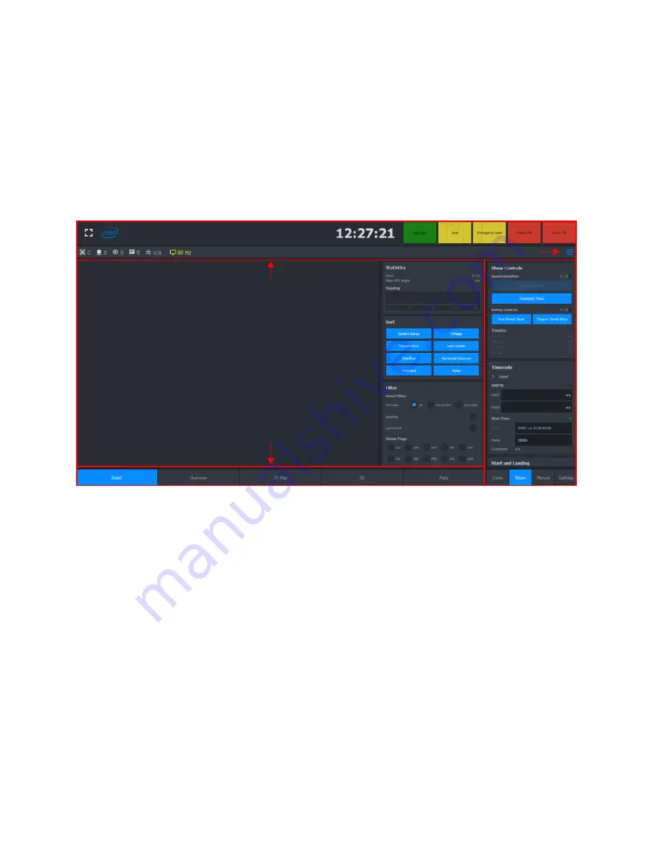
2.3.1 User Interface 

The following picture shows the user interface (UI) of the Control Center. There are four main groups. 

Figure 2-1. Control Center UI Layout 


2.3.1.1


Top Bar 

The Top Bar provides access to key commands, such as Land, Emergency Land and Power Off.  It also 
displays the total number of Drones available, and provides a button on the right-hand side to upload 
.JSON settings files which can pre-load settings into the Show tab found in the Side View

2.3.1.2


Bottom Bar 

The Bottom Bar tabs can be used to switch between different Main View modes. 

2.3.1.3


Main View 

The Main View will show data regarding the fleet as specified by the Bottom Bar, such as the status of 
each Drone in Detail mode and a general overview of the Drones in Overview mode. 

2.3.1.3.1


Detail 

In this mode of the Main View, all Drones will be shown in a list. Each Drone is represented by a box, 
which expands if it is selected. It will collapse again if it is unselected. 

Last Update: The time passed since an update was received from the Drone. 

Voltage: The voltage is the battery voltage at the time the last update was received. 

Main View 

Top Bar 

Bottom Bar 

Side View 

Settings file 

Summary of Contents for Shooting Star Mini

Page 1: ...ick Start Guide October 23 2018 Intel Confidential WARNING READ MANUAL BEFORE USE THIS EQUIPMENT MAY ONLY BE OPERATED INDOORS OPERATION OUTDOORS IS IN VIOLATION OF 47 U S C 301 AND COULD SUBJECT THE O...

Page 2: ...17 2018 1 3 Incorporated Safety information July 22 2018 1 4 Warnings and Regulatory Statements added Handling and Storage Instructions added Appendix removed Aug 17 2018 1 5A Added Information to the...

Page 3: ...er 10 3 Basic Operations 12 3 1 Simple Test Flight 12 3 2 Basic Animation Flight 12 4 Regulatory and Safety Information 14 5 Drone Battery Handling Precautions and Guidelines 17 Figures 1 1 ILT Hardwa...

Page 4: ...aunchpads 2 Provides guidance on how to set up and use the Indoor Location Technology system 3 Demonstrates the basic features of the Intel Shooting Star Mini Control Center software 4 Walks through a...

Page 5: ...errupter GFCI is required Each Launchpad features 2 powerCON True1 connectors and can be individually connected to a power outlet or grouped together The number of hubs connected to a power outlet is...

Page 6: ...lines The minimum space that the ILT system can operate in with stable performance is 5 meters along each dimension X Y Z Anchors should be positioned every 30 35 meters The current build will support...

Page 7: ...f a drone within your space but you may need to install more anchors to improve the accuracy and redundancy of your network When placing anchors on the ceiling and floor planes we recommend choosing t...

Page 8: ...icate to the Drones This communication link can be established via Ethernet once the ILT network has been configured 1 Plug in and turn on the Network Server and then attach the sniffer device using a...

Page 9: ...a particular anchor or tag in a different color you can use this feature to perform a dynamic test of the network Power on a tag The system will automatically detect the tag and show it in the GUI Ne...

Page 10: ...tton on the right hand side to upload JSON settings files which can pre load settings into the Show tab found in the Side View 2 3 1 2 Bottom Bar The Bottom Bar tabs can be used to switch between diff...

Page 11: ...e Drones via ILT Start and Landing Compute This will initiate the optimisation algorithm and allocate the specific Drones to be used for the flight Start and Landing Transmit Optimisation This will tr...

Page 12: ...m This section will not describe in detail how to perform a light show but it will describe the basic steps to perform a flight if the animation file and the parameters file for the specific location...

Page 13: ...Verify that necessary number of Drones have been armed 22 Supervise the launch and verify that all Drones have launched successfully 23 Supervise the animation flight and watch for any Warning Error...

Page 14: ...hout wearing safety gloves PSE Li Ion Battery risk of fire Do not open crush or heat o The battery may explode or cause burns if disassembled crushed or exposed to fire or high temperatures Do not sho...

Page 15: ...orrect the interference by one or more of the following measures Reorient or relocate the receiving antenna Increase the separation between the equipment and receiver Connect the equipment into an out...

Page 16: ...d to perform typical tasks and to operate safely o Safety Briefing and safety training is mandatory o If interacting with performers a choreography shall be developed and trained and rehearsals shall...

Page 17: ...rge is suggested under 5 and above 45 Discharge under too low or too high temperatures could lead to drone battery failure or other conditions Storage When voltage is 3 7V 3 9V the drone battery could...

Reviews: