background image

Hardware Installations and Upgrades

32

Intel® Entry Server Chassis SC5299-E DP/WS/BRP User Guide

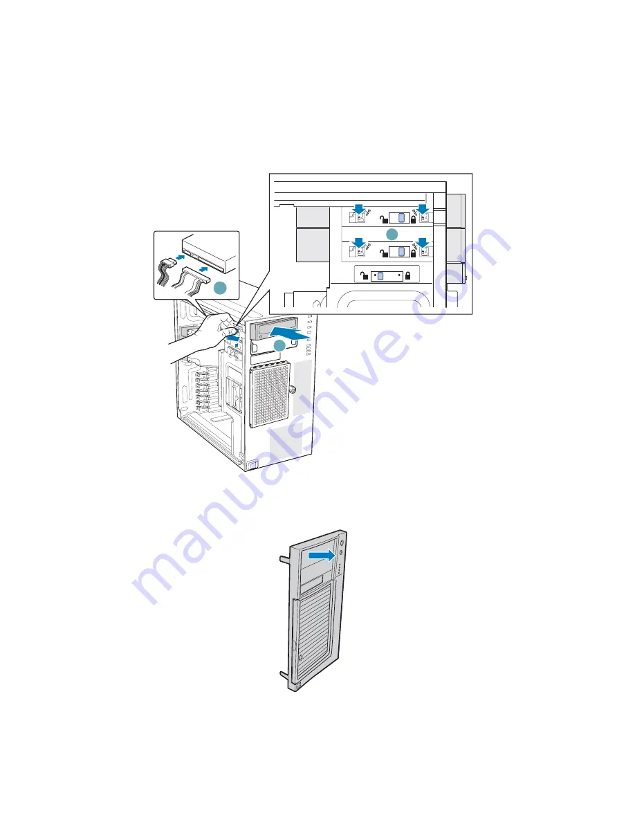
6. Insert CD-ROM or DVD-ROM drive into the 5.25-in device drive bay (see letter “C” 

in the following figure). Line up holes in CD-ROM drive with holes in chassis (see 
letter “D”). Move latch to the “lock” position (see letter “E”). Connect power (P3 or 
P4 connector from the power supply) and data cables to the rear of the CD-ROM or 
DVD-ROM drive (see letter “F”).

Figure 36.  Installing CD-ROM or DVD-ROM Drive

7. If necessary, remove the filler panel from the front bezel assembly.

C

E

F

D

TP01064

TP01723

Summary of Contents for SC5299-E BRP

Page 1: ...Intel Entry Server Chassis SC5299 E DP WS BRP User Guide A Guide for Technically Qualified Assemblers of Intel Identified Subassemblies Products Intel Order Number D37596 002...

Page 2: ...Intel may make changes to specifications and product descriptions at any time without notice Intel server boards contain a number of high density VLSI and power delivery components that need adequate...

Page 3: ...usen auf der Intel Server Deployment Toolkit CD oder unter http support intel com support motherboards server sb cs 010770 htm Consignes de s curit Lisez attention toutes les consignes de s curit et l...

Page 4: ...y or equipment damage can result Electrostatic discharge ESD and ESD protection ESD can damage disk drives boards and other parts We recommend that you perform all procedures in this chapter only at a...

Page 5: ...oduct and product diagrams to help you identify components and their locations Chapter 2 provides instructions on adding and replacing components Use this chapter for step by step instructions and dia...

Page 6: ...rmation and Software If you need more information about this product or information about the accessories that can be used with this server chassis use the following resources These files are availabl...

Page 7: ...ted with this product Tested Hardware Operating Systems List To make sure your system falls within the allowed power budget Power Budget Tool at http support intel com support motherboards server chas...

Page 8: ...Preface viii Intel Entry Server Chassis SC5299 E DP WS BRP User Guide...

Page 9: ...Mounted Systems 9 Mechanical Locks 10 Accessories and Order Codes 10 Hardware Installations and Upgrades 11 Before You Begin 11 Tools and Supplies Needed 11 System References 11 Removing and Installin...

Page 10: ...e 56 Installing a Hot Swap Hard Drive 67 Rack Mount Kit Install Instructions optional 75 Before You Begin 75 Tools and Supplies Needed 75 System References 75 Setting up a Rack configured Chassis 75 T...

Page 11: ...s lectrostatiques ESD 106 Autres risques 107 Espa ol 108 Informaci n de seguridad del servidor 108 Advertencias y precauciones sobre seguridad 108 Aplicaciones y usos previstos 109 Selecci n de la ubi...

Page 12: ...roduct EMC Compliance Class A Compliance 144 Certifications Registrations Declarations 144 Product Regulatory Compliance Markings 145 Electromagnetic Compatibility Notices 146 FCC Verification Stateme...

Page 13: ...19 Inserting Fixed Hard Drive Cage into Chassis 20 Figure 20 Re attaching Drive Cage EMI Shield 21 Figure 21 Drive Bay Slot Order 22 Figure 22 Removing Drive Cage EMI Shield from Chassis 23 Figure 23...

Page 14: ...s 50 Figure 65 Removing Rear Support Bracket from Hot Swap Power Supply Cage 51 Figure 66 Attaching Rear Support Bracket to Power Supply Cage 51 Figure 67 Securing Hot Swap Power Supply Cage to Rear o...

Page 15: ...stalling Drive Carrier in Hot Swap Drive Cage 73 Figure 96 Closing Drive Bay Access Door 73 Figure 97 Removing Chassis Feet 76 Figure 98 Removing Top Side Cover from Chassis 76 Figure 99 Removing PCI...

Page 16: ...xvi Intel Entry Server Chassis SC5299 E DP WS BRP User Guide...

Page 17: ...Configurations 1 Table 2 Server Chassis Features 2 Table 3 Accessories and Order Codes 10 Table 4 550 W Power Supply Output Capability 87 Table 5 670 W Power Supply Output Capability 88 Table 6 650 W...

Page 18: ...xviii Intel Entry Server Chassis SC5299 E DP WS BRP User Guide...

Page 19: ...5000VSA The type of server board supported is dependent upon the configuration purchased See Table 1 for a list of the Intel server boards that are supported by each server chassis configuration AF000...

Page 20: ...to replace the fixed hard drive cage Peripherals Two tool less 5 25 in device drive bays for CD ROM DVD ROM drive or tape drive Front panel One for the DP WS BRP chassis configurations Front Panel LED...

Page 21: ...5299 E DP WS BRP User Guide 3 Component Identification Front View Components Figure 2 Front View Components with Front Bezel Assembly A 5 25 in Device Drive Bays B Front Panel C Drive Bay Access Door...

Page 22: ...Chassis SC5299 E DP WS BRP User Guide Figure 3 Front View Components without Front Bezel Assembly A 5 25 in Device Drive Bays B 3 5 in Device Drive Bay C Hard Drive Cage D Drive Bay EMI Shield shown o...

Page 23: ...less Device Bay Locks B 5 25 in Device Bays C 3 5 in Device Bay D Drive Bay EMI Shield E Drive Cage Retention Mechanism F PCI Add in Card Guide G Front Panel USB Ports H Fixed Hard Drive Cage I Large...

Page 24: ...NOTE Fixed Power Supply shown Your Power Supply may vary depending on chassis configuration purchased C Alternate external SCSI knockout D System Fan E I O Shield NOTE I O connectors vary depending o...

Page 25: ...zes the system E F NIC 1 Activity LED NIC 2 Activity LED Continuous green light indicates a link between system and network Blinking green light indicates network activity No light indicates the NIC i...

Page 26: ...7 Optional Peripheral Devices Hard Disk Drives The server chassis ships with one fixed hard drive cage capable of supporting up to six cabled 3 5 in x 1 in hard drives Power requirements for each ind...

Page 27: ...ormation and Software for an web link to a list of supported hardware Front Bezel Assembly The front bezel assembly provides a snap on design that allows for maximum airflow through the server chassis...

Page 28: ...cal lock see letter B on the front bezel assembly to prevent access to the hard drives and the interior of the chassis Figure 8 Mechanical Locks Accessories and Order Codes For a complete list of spar...

Page 29: ...top and bottom assume the reader is facing the front of the chassis as it would be positioned for pedestal operation Removing and Installing the Left Side Cover Warning This chassis must be operated w...

Page 30: ...e the left side cover rearward to remove from chassis see letter C Figure 9 Removing Left Side Cover Installing the Left Side Cover Warning This chassis must be operated with the left side cover insta...

Page 31: ...rmation 2 Turn off all peripheral devices connected to the server Turn off the server 3 Disconnect the AC power cord 4 Remove the left side cover For instructions see Removing the Left Side Cover 5 Di...

Page 32: ...lowing figure Engage the clips with the slots see letter B Rotate the left side of the the front bezel assembly towards the chassis see letter C Snap the two bezel tabs into the corresponding recesses...

Page 33: ...essor and heat sink Removing the Processor Air Duct 1 Observe the safety and ESD precautions listed in Appendix A Safety Information 2 Power down the server and unplug all peripheral devices and the A...

Page 34: ...l in your chassis will depend upon the model of chassis you purchased For a breakout of server board chassis model compatibility see Table 1 Breakdown of Intel Entry Server Chassis SC5299 E Configurat...

Page 35: ...e drive cage EMI shield see letter A in the following figure Figure 15 Removing Drive Cage EMI Shield from Fixed Drive Cage 6 Disconnect cables from any installed fixed hard drives If necessary remove...

Page 36: ...in the following figure Once released pull the fixed hard drive cage from the chassis see letter B Figure 16 Removing Fixed Hard Drive Cage 8 Remove any PCI add in boards that are present 9 Remove the...

Page 37: ...roperly seated and then tighten the screws firmly starting with the screws at the center of the server board If removing a server board disconnect all cables connected to the server board Refer to you...

Page 38: ...cage into the drive bay slot of the chassis You should hear a click when the blue plastic retention mechanism locks into place Figure 19 Inserting Fixed Hard Drive Cage into Chassis 15 If previously r...

Page 39: ...ighten the thumb screw Figure 20 Re attaching Drive Cage EMI Shield 17 Re install the front bezel assembly For instructions see Removing and Installing the Front Bezel Assembly 18 Re install the left...

Page 40: ...ink to a list of supported hard drives Installing a Fixed Hard Drive Caution Fixed drives are NOT hot swappable Before removing or replacing the drive you must first take the server out of service tur...

Page 41: ...de Cover 4 Remove the front bezel assembly For instructions see Removing the Front Bezel Assembly 5 Loosen thumb screw and remove the drive cage EMI shield see letter A in the following figure Figure...

Page 42: ...lue tabs see letter A in the following figure and pulling the PCI card guide outward see letter B Figure 23 Removing PCI Card Guide 8 Route the required power cables connectors P8 P13 from behind the...

Page 43: ...latch the drive locking assembly for the drive bay you want to install a hard drive in Figure 25 Unlatching Drive Latch 10 Insert fixed hard drive into drive bay and push until it stops Ensure that th...

Page 44: ...ive latch in to lock hard drive into drive bay Figure 27 Latching Drive Latch 12 Install additional drives as necessary Warning Drive bay slots 1 3 and 5 MUST be populated first Failure to do so could...

Page 45: ...ing figure and data see letter B cables to each of the installed drives The cables route through the oval opening at the bottom of the fixed drive cage Figure 29 Cabling a Fixed Hard Drive 14 Re attac...

Page 46: ...see Installing the Left Side Cover 19 Plug all peripheral devices and the AC power cable back into the server Power up the server Removing a Fixed Hard Drive Caution Fixed drives are NOT hot swappabl...

Page 47: ...o right side of drive bay access door and swing door outward see letter B 6 Disconnect the data and power cables from the hard drive to be removed see letter A in the following figure Pull the drive l...

Page 48: ...stalling a Fixed Hard Drive for instructions Figure 33 Removing Fixed Hard Drive from Drive Bay 8 Re attach the drive cage EMI shield to the chassis and tighten the thumb screw Figure 34 Re installing...

Page 49: ...by pressing the power button and unplug the AC power cord from the system or wall outlet Installing a DVD ROM or CD ROM Drive 1 Observe the safety and ESD precautions listed in Appendix A Safety Infor...

Page 50: ...owing figure Line up holes in CD ROM drive with holes in chassis see letter D Move latch to the lock position see letter E Connect power P3 or P4 connector from the power supply and data cables to the...

Page 51: ...ety and ESD precautions listed in Appendix A Safety Information 2 Power down the server and unplug all peripheral devices and the AC power cable 3 Remove the chassis cover For instructions see Removin...

Page 52: ...I add in board in the Intel Entry Server Chassis SC5299 E These instructions are server board dependent See your server board documentation to determine PCI add in board compatibility Caution Do not o...

Page 53: ...ard Retention Device 5 Remove the PCI slot shield if it has not already been removed by pushing the shield out from the inside of the chassis Figure 40 Removing PCI Slot Shield 6 Remove a PCI add in b...

Page 54: ...stalling the Left Side Cover 11 Reconnect all peripheral devices and the AC power cable Power up the server Removing PCI Add in Boards Caution PCI add in boards can be extremely sensitive to electric...

Page 55: ...e 5 Disconnect any cables that may be attached to the PCI add in board that needs to be removed 6 Firmly grab the PCI add in board by its top edge or upper corners and remove from the expansion slot o...

Page 56: ...rd installed Caution The front panel board is NOT hot swappable Before removing or replacing the front panel board you must first take the server out of service turn off all peripheral devices connect...

Page 57: ...see letter A in the following figure securing the right side cover to the chassis Lift the right side cover off the chassis Figure 45 Removing Right Side Cover from Chassis 6 Remove the three screws...

Page 58: ...t side of the chassis see letter A in the following figure Disconnect the front panel cable see letter B and the chassis intrusion cable see letter C from the front panel board Figure 47 Removing Fron...

Page 59: ...front panel board Slide the new front panel board through the opening in the left side of chassis see letter C Figure 49 Installing Front Panel Board in Chassis 10 Use one hand to align the front pan...

Page 60: ...14 Reconnect all peripheral devices and the AC power cable Power up the server Replacing a System Fan Caution The system fan for the Intel Entry Server Chassis SC5299 E is NOT hot swappable Before re...

Page 61: ...ver Chassis SC5299 E DP WS BRP User Guide 43 4 Remove the fan duct system fan assembly Figure 52 Removing Fan Duct System Fan Assembly 5 Re install the fan duct system fan assembly Figure 53 Re instal...

Page 62: ...r supply is NOT hot swappable in the DP and WS models of the Intel Entry Server Chassis SC5299 E Before removing or replacing the fixed power supply you must first take the server out of service turn...

Page 63: ...he power supply out of the chassis Figure 55 Removing Fixed Power Supply from Chassis 7 Insert new fixed power supply in chassis Ensure that the blue locking mechanism is still in the open position Ma...

Page 64: ...tart User s Guide or User Guide that came with your Intel server board for appropriate power connections 10 Route the P5 cable to the floppy drive 11 Route the P3 and P4 cables to the 5 25 in removabl...

Page 65: ...pply Hazardous voltage current and energy levels are present inside the power supply There are no user serviceable parts inside it servicing of the power supply should be done only by technically qual...

Page 66: ...done only by technically qualified personnel 1 Observe the safety and ESD precautions listed in Appendix A Safety Information 2 Remove power cable from defective power supply 3 Press up on green latc...

Page 67: ...ersonnel 1 Observe the safety and ESD precautions listed in Appendix A Safety Information 2 Power down the server and unplug all peripheral devices and the AC power cable 3 Remove the left side cover...

Page 68: ...re 63 Detaching Hot Swap Power Supply Cage from Inside of Chassis 8 Remove five external screws securing back of power supply cage to chassis Slide the power supply cage out of the chassis Note You ma...

Page 69: ...the rear support bracket to the old power supply cage Remove the rear support bracket see letter B Figure 65 Removing Rear Support Bracket from Hot Swap Power Supply Cage 10 Attach the rear support br...

Page 70: ...hassis with five screws Note Ensure that you route the power supply cables through the power supply opening in the chassis first before inserting the power supply cage Figure 67 Securing Hot Swap Powe...

Page 71: ...ard drive cage and connect power cables to any installed devices 15 Route the P3 and P4 cables to the 5 25 in removable media device bays and connect to any installed devices 16 Route the P5 cable to...

Page 72: ...tions listed in Appendix A Safety Information 2 Power down the server and unplug all peripheral devices and the AC power cable 3 Lay the chassis down on its right side 4 Insert rubber foot into chassi...

Page 73: ...onal Information and Software for a web link to a list of supported hard drives Before You Begin Before working with your server product review the important safety information listed in Appendix A Sa...

Page 74: ...al devices and the AC power cable 3 Remove the left side cover For instructions see Removing the Left Side Cover 4 Remove the front bezel assembly For instructions see Removing the Front Bezel Assembl...

Page 75: ...ve cage see letter A in the following figure Once released pull the fixed hard drive cage from the chassis see letter B Figure 72 Removing Fixed Hard Drive Cage from Chassis 8 Gather together the comp...

Page 76: ...5299 E DP WS BRP User Guide 9 Remove the stud screws from the top of the hot swap drive cage Figure 73 Removing Stud Screws from Hot Swap Drive Cage 10 Attach the latch plate to the left side of the h...

Page 77: ...BRP User Guide 59 11 Attach the side filler panel to the right side of the hot swap drive cage Figure 75 Attaching Filler Panel to Hot Swap Drive Cage 12 Remove the two thumb screws that secure the b...

Page 78: ...see letter A in the following figure and slide the fan bracket into position Replace the two thumb screws see letter B Caution The backplane may have slipped once the thumb screws were removed Ensure...

Page 79: ...ch the fan to the fan bracket by placing two corners of the fan into the two holding slots on the fan bracket Press the fan into the fan bracket until is clicks into place Caution Ensure that the labe...

Page 80: ...retention mechanism locks into place Be sure to feed the fan cable through the slot first so that it exits through the back of the drive cage Connect the fan cable to its connector on the server board...

Page 81: ...ard or RAID controller card Failure to do so may result in data loss Note Connect the SES cable from the backplane to the RAID card if one is installed a If you are installing a six drive SCSI hot swa...

Page 82: ...ntroller card Failure to do so may result in data loss Note The SAS SATA cables are labeled to correspond with each drive Make sure to connect the cables correctly to avoid confusion later The SAS SAT...

Page 83: ...SATA data cable see letter B to each appropriate SAS SATA connector on the SAS SATA backplane iii Connect the IPMB cable see letter C iv Connect the SES cable see letter D v Connect the fan power to...

Page 84: ...ct the fan power to the server board For the Intel Server Board S5000VSA use FAN1 For other Intel server boards refer to the Quick Start User s Guide that came with the server board Figure 83 Making S...

Page 85: ...drive cage that shipped with your chassis with an optional hot swap SCSI or SAS SATA hard drive cage If you are replacing a fixed hard drive see Removing a Fixed Hard Drive for instructions Note The I...

Page 86: ...of the drive cage Figure 85 Releasing Drive Carrier from Hot Swap Drive Cage 3 Remove the four screws that attach the plastic retention device to the drive carrier Two screws are located on each side...

Page 87: ...nstalling Hard Drive into Drive Carrier 8 With the black lever in the fully open position insert the drive carrier into the hot swap drive cage The green latch at the front of the drive carrier must b...

Page 88: ...70 Intel Entry Server Chassis SC5299 E DP WS BRP User Guide 9 Close the drive bay access door Figure 89 Closing Drive Bay Access Door Removing a Hot swap Hard Drive 1 Open the drive bay access door F...

Page 89: ...in the following figure Pull out on the black lever see letter B to slide the drive carrier from the hot swap drive cage Figure 91 Removing Drive Carrier from Hot Swap Drive Cage 3 Remove the four scr...

Page 90: ...with the screws removed in the previous step Note If you are not installing a new drive place a plastic retention device into the drive carrier using the four screws you removed from the hard drive Fi...

Page 91: ...DP WS BRP User Guide 73 Note For proper airflow the drive carrier must be replaced in the chassis even if no hard drive is installed in it Figure 95 Re installing Drive Carrier in Hot Swap Drive Cage...

Page 92: ...Hot Swap Drive Cage Upgrade Install Instructions optional 74 Intel Entry Server Chassis SC5299 E DP WS BRP User Guide...

Page 93: ...ormation Tools and Supplies Needed Phillips cross head screwdriver 1 bit and 2 bit Needle nosed pliers Anti static wrist strap and conductive foam pad recommended System References All references to l...

Page 94: ...m rubber foot see letter A in the following figure Remove rubber foot from chassis hole see letter B Repeat process for remaining feet Figure 97 Removing Chassis Feet 5 Remove the top side cover by pr...

Page 95: ...Chassis SC5299 E DP WS BRP User Guide 77 6 Remove any PCI add in boards Remove the PCI card guide by pressing in on the blue tabs see letter A in the following figure and pulling the PCI card guide ou...

Page 96: ...ssis SC5299 E DP WS BRP User Guide 7 Remove plastic filler panel from chassis by pushing on interior tab see letter A in the following figure and sliding filler panel towards rear of chassis see lette...

Page 97: ...ntry Server Chassis SC5299 E DP WS BRP User Guide 79 8 Remove the three plastic plugs from left side of chassis Figure 101 Removing Plastic Plugs 9 Remove two screws from left and right sides of chass...

Page 98: ...sis SC5299 E DP WS BRP User Guide 10 Remove four plastic plugs from top side cover Figure 103 Removing Plastic Plugs from Top Side Cover 11 Install rack handle on left side cover using four 6 32 screw...

Page 99: ...zel assembly Affix front panel label see letter A in the following figure to the front panel Figure 105 Affixing Label to Front Panel 13 Install top side cover on chassis Warning This chassis must be...

Page 100: ...el Entry Server Chassis SC5299 E DP WS BRP User Guide 14 Detach inner rack rail from rack rail assembly Press tab on inside of rack rail to release rack rail from rack rail assembly Figure 107 Detachi...

Page 101: ...ack rails one per side to chassis with four 6 32 screws Figure 108 Attaching Inner Rack Rails to Chassis 16 Attach outer rack rails to rack uprights Ensure that the screws two per outer rack rail see...

Page 102: ...Rack Mount Kit Install Instructions optional 84 Intel Entry Server Chassis SC5299 E DP WS BRP User Guide Figure 109 Attaching Outer Rack Rails to Rack Uprights TP01056 B C A...

Page 103: ...e 85 17 Install chassis into rack Warning Safe handling and lifting of this system requires TWO people Figure 110 Installing Chassis into Rack 18 Reconnect all peripheral devices and the AC power cabl...

Page 104: ...Rack Mount Kit Install Instructions optional 86 Intel Entry Server Chassis SC5299 E DP WS BRP User Guide...

Page 105: ...of chassis you purchased Four power supply configurations are available 550 W PFC fixed power supply DP configuration 650 W PFC redundant power supply BRP configuration 670 W PFC fixed power supply WS...

Page 106: ...ly Input Voltages 100 127V at 50 60 Hz 9 63 Arms max 200 240V at 50 60 Hz 4 82 Arms max 650 W Single Power Supply Output Voltages The following table lists the total amperage available from the power...

Page 107: ...rating Operating 40 to 70 C 10 to 35 C derated 0 5 C for every 1000 ft 305 m to a maximum of 10 000 ft Humidity Non operating 90 relative humidity non condensing at 30 C Shock Operating Packaged 2 0 g...

Page 108: ...Technical Reference 90 Intel Entry Server Chassis SC5299 E DP WS BRP User Guide...

Page 109: ...onents specified in this guide Use of other products components will void the UL Listing and other regulatory approvals of the product and may result in noncompliance with product regulations in the r...

Page 110: ...s that are susceptible to electrical storms we recommend you plug your system into a surge suppresser and disconnect telecommunication lines to your modem during an electrical storm Provided with a pr...

Page 111: ...AC power cord was not provided with your product purchase one that is approved for use in your country Caution To avoid electrical shock or fire check the power cord s that will be used with the produ...

Page 112: ...rate the system without the fan guard in place Rack Mount Warnings The equipment rack must be anchored to an unmovable support to prevent it from tipping when a server or piece of equipment is extende...

Page 113: ...irflow Caution Carefully route cables as directed to minimize airflow blockage and cooling problems For proper cooling and airflow operate the system only with the chassis covers installed Operating t...

Page 114: ...ung anderer Produkte oder Komponenten f hrt zum Erl schen der UL Zulassung und anderer Genehmigungen f r das Produkt Dadurch kann das Produkt gegen Produktbestimmungen versto en die im Verkaufsland ge...

Page 115: ...Vibrations oder Ersch tterungsquellen Abgeschirmt von starken elektromagnetischen Feldern die durch elektrische Ger te erzeugt werden In gewittergef hrdeten Gebieten sollten Sie das System an einen b...

Page 116: ...gewartet werden k nnen ffnen Sie das Netzteil nicht Im Netzteil bestehen gef hrliche Spannungen Str me und Energiequellen Schicken Sie das Ger t f r Wartungsarbeiten an den Hersteller zur ck Wenn Sie...

Page 117: ...n bzw befestigungselementen F hren Sie keine Arbeiten im Netzteil aus Das Netzteil enth lt keine f r den Benutzer wartungsbed rftigen Teile Schicken Sie das Ger t f r Wartungsarbeiten an den Herstelle...

Page 118: ...und alle darin eingebauten Ger te ordnungsgem geerdet sein Elektrostatische Entladungen ESD Vorsicht Elektrostatische Entladungen k nnen zur Besch digung von Festplatten Platinen und anderen Komponen...

Page 119: ...ns darf das System nur mit angebrachten Geh useabdeckungen betrieben werden Die Inbetriebnahme des Systems ohne Abdeckung kann zur Besch digung von Systemkomponenten f hren So bringen Sie die Abdeckun...

Page 120: ...utres approbations r glementaires du produit et le produit peut ne pas tre conforme aux autres lois et r glementations locales applicables au produit S curit avertissements et mises en garde Pour vite...

Page 121: ...art des sources de chaleur telles que la lumi re directe du soleil et les radiateurs l cart des sources de vibration ou des chocs physiques Isol des champs lectromagn tiques importants produits par de...

Page 122: ...de probl me Lorsque vous remplacez un bloc d alimentation chaud d branchez le cordon du bloc d alimentation en cours de remplacement avant de le retirer du serveur Pour viter tout risque d lectrocutio...

Page 123: ...ieur du bloc d alimentation Il ne contient aucune pi ce r parable Renvoyez le au fabricant en cas de probl me Mettez le serveur hors tension et d branchez tous les cordons d alimentation avant d ajout...

Page 124: ...ll dans le rack doivent tre correctement reli s la terre D charges lectrostatiques ESD Attention Les d charges lectrostatiques ESD peuvent endommager les lecteurs de disque dur les cartes et d autres...

Page 125: ...les probl mes de refroidissement Afin de permettre une ventilation et un refroidissement corrects ne mettez le syst me en marche que lorsque les panneaux du ch ssis sont en place L utilisation du sys...

Page 126: ...os o componentes anular la homologaci n UL y otras certificaciones oficiales del producto pudiendo dejar de ser compatible con las normativas locales de los pa ses en los que se comercializa Advertenc...

Page 127: ...aci n Bien ventilada y alejada de fuentes de calor incluida la luz solar directa y los radiadores Alejada de fuentes de vibraci n o de golpes f sicos Aislada de campos electromagn ticos producidos por...

Page 128: ...haber niveles de tensi n corriente y energ a peligrosos Devu lvala al fabricante para repararla Al reemplazar una fuente de alimentaci n de conexi n en funcionamiento desenchufe el cable de alimentaci...

Page 129: ...te de alimentaci n No hay elementos en la fuente de alimentaci n que usted pueda reparar y utilizar Devu lvala al fabricante para repararla Apague el servidor y desconecte todos los cables de alimenta...

Page 130: ...el ctricas deber instalar una conexi n a tierra apropiada para el bastidor y para cada pieza del equipo instalada en el mismo Descarga electrost tica ESD Precauci n Las descargas electrost ticas pued...

Page 131: ...a ventilaci n y de refrigeraci n Para conseguir una refrigeraci n y corriente de aire adecuadas compruebe que cuando sistema est funcionando las cubiertas de la carcasa est n instaladas Si utiliza el...

Page 132: ...Safety Information 114 Intel Entry Server Chassis SC5299 E DP WS BRP User Guide Intel Intel Intel Web UL...

Page 133: ...Safety Information Intel Entry Server Chassis SC5299 E DP WS BRP User Guide 115 ITE ITE 5V...

Page 134: ...Safety Information 116 Intel Entry Server Chassis SC5299 E DP WS BRP User Guide...

Page 135: ...Safety Information Intel Entry Server Chassis SC5299 E DP WS BRP User Guide 117 ESD ESD ESD ESD ESD...

Page 136: ...Safety Information 118 Intel Entry Server Chassis SC5299 E DP WS BRP User Guide...

Page 137: ...ear the equipment and shall be easily accessible SAFETY STEPS Whenever you remove the chassis covers to access the inside of the system follow these steps 1 Turn off all peripheral devices connected t...

Page 138: ...n some board and chassis parts Contact should be made with care Consider wearing protective gloves Danger of explosion if the battery is incorrectly replaced Replace only with the same or equivalent t...

Page 139: ...geschaltet Ziehen Sie jedes Wechselstrom Netzkabel aus der Steckdose bzw dem Netzger t um den Stromanschlu des Systems zu unterbrechen SICHERHEISMASSNAHMEN Immer wenn Sie die Geh useabdeckung abnehmen...

Page 140: ...eile darin besch digen Um die Abdeckung wieder anzubringen 1 Vergewissern Sie sich da Sie keine Werkzeuge oder Teile im Innern des Systems zur ckgelassen haben 2 berpr fen Sie alle Kabel Zusatzkarten...

Page 141: ...n Ersch tterungen ausgesetzt sein keine starken von elektrischen Ger ten erzeugten elektromagnetischen Felder aufweisen in Regionen in denen elektrische St rme auftreten mit einem berspannungsschutzge...

Page 142: ...vrez le bo tier pour acc der l int rieur du syst me suivez les consignes suivantes 1 Mettez hors tension tous les p riph riques connect s au syst me 2 Mettez le syst me hors tension en mettant l inter...

Page 143: ...Faites galement attention aux broches aigu s des cartes et aux bords tranchants du capot Nous vous recommandons l usage de gants de protection Danger d explosion si la batterie n est pas remont e corr...

Page 144: ...SEGURIDAD Cuando extraiga la tapa del chasis para acceder al interior del sistema siga las siguientes instrucciones 1 Apague todos los dispositivos perif ricos conectados al sistema 2 Apague el siste...

Page 145: ...lientes Tambi n conviene tener en cuenta que en el chasis o en el tablero puede haber piezas cortantes o punzantes Por ello se recomienda precauci n y el uso de guantes protectores Existe peligro de e...

Page 146: ...rture del telaio per accedere all interno del sistema seguire i seguenti passi 1 Spegnere tutti i dispositivi periferici collegati al sistema 2 Spegnere il sistema usando il pulsante spento acceso del...

Page 147: ...trebbero essere surriscaldati Fare attenzione alla presenza di piedini appuntiti e parti taglienti sulle schede e sul telaio consigliabile l uso di guanti di protezione Esiste il pericolo di un esplos...

Page 148: ...Installation Assembly Safety Instructions 130 Intel Entry Server Chassis SC5299 E DP WS BRP User Guide...

Page 149: ...or telephone support at any time without notice Before calling fill out an Intel Server Issue Report Form A sample form is provided on the following pages However for the fastest service please submit...

Page 150: ...Myanmar 63 2 636 9796 via Philippines New Zealand 0800 444 365 Pakistan 632 63684 15 IDD via Philippines Philippines 1 800 1 651 0117 Singapore 65 6213 1311 Taiwan 2 2545 1640 Thailand 1 800 631 0003...

Page 151: ...al 800 843 4481 Pacifictel Contact AT T USA at 1 800 225 528 Once connected dial 800 843 4481 Guatemala Contact AT T USA at 99 99 190 Once connected dial 800 843 4481 Mexico Contact AT T USA at 001 80...

Page 152: ...Getting Help 134 Intel Entry Server Chassis SC5299 E DP WS BRP User Guide...

Page 153: ...brief description below See the last page for space to include a detailed problem description ____________________________________________________________________ _____________________________________...

Page 154: ...______________________________ DIMM4B MB and Vendor part number __________________________________ Operating System Information Operating System _____________________________________________________ V...

Page 155: ...ional Edition____________________________ Intel Management Module Advanced Edition _____________________________ Control Panel Information Standard Control Panel ______________________________________...

Page 156: ...___________________________ ____________________________________________________________________ ____________________________________________________________________ __________________________________...

Page 157: ...duct is defective transportation charges for the return of Product to buyer within the USA will be paid by Intel For all other locations the warranty excludes all costs of shipping customs clearance a...

Page 158: ...ny costs of recovering reprogramming or reproducing any program or data stored in or used with a system containing this product Some jurisdictions do not allow the exclusion or limitation of incidenta...

Page 159: ...ns for the remainder of the original warranty period Telephone Support If you cannot find the information you need on Intel s World Wide Web site http www intel com call your local distributor or an I...

Page 160: ...Warranty 142 Intel Entry Server Chassis SC5299 E DP WS BRP User Guide...

Page 161: ...his server board The final configuration of your end system product may require additional EMC compliance testing For more information please contact your local Intel representative This is an FCC Cla...

Page 162: ...r Builder Web site or contact your local Intel representative FCC ICES 003 Emissions USA Canada Verification CISPR 22 Emissions International EN55022 Emissions Europe EN55024 Immunity Europe EN61000 3...

Page 163: ...s Certification License Belarus RRL Certification Korea IRAM Certification Argentina CNCA Certification China Ecology Declaration International Product Regulatory Compliance Markings This Intel server...

Page 164: ...ant to Part 15 of the FCC Rules These limits are designed to provide reasonable protection against harmful interference in a residential installation This equipment generates uses and can radiate radi...

Page 165: ...TV reception All cables used to connect to peripherals must be shielded and grounded Operation with cables connected to peripherals that are not shielded and grounded may result in interference to ra...

Page 166: ...a English translation of the notice above 1 Type of Equipment Model Name On License and Product 2 Certification No On RRL certificate Obtain certificate from local Intel representative 3 Name of Certi...

Page 167: ...imum power rating of any one device is 19 watts Total server configuration is not to exceed the maximum loading conditions of the power supply Restriction of Hazardous Substances RoHS Compliance Intel...

Page 168: ...Regulatory and Compliance Information 150 Intel Entry Server Chassis SC5299 E DP WS BRP User Guide...

Reviews: