


Intel® Server Chassis SC1400UP / Intel® Server Platform SR1425BK1-E
Revision 1.0
- 26 -
3.1.1.2
CDROM or DVD-CDR Drive Use with or without Backplane present
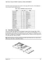
Regardless of whether a backplane is present or not, the slim-line CDROM or DVD-CDR drive
is mated with an interposer card which provides the power and IO interconnects between the
drive, power supply and baseboard. The interposer card has three connectors; the first has 50
pins and is plugged directly into the drive connector. The connector has the following pinout.
Table 5. 50-pin CD-ROM connector Pinout (J6)
Name
Pin
Pin
Name
RSV_LCM 1
2
RSV_RCM
RSV_GND 3
4
GND
RST_IDE_S_L 5
6
IDE_SDD<8>
IDE_SDD<7> 7
8
IDE_SDD<9>
IDE_SDD<6> 9
10
IDE_SDD<10>
IDE_SDD<5> 11
12
IDE_SDD<11>
IDE_SDD<4> 13
14
IDE_SDD<12>
IDE_SDD<3> 15
16
IDE_SDD<13>
IDE_SDD<2> 17
18
IDE_SDD<14>
IDE_SDD<1> 19
20
IDE_SDD<15>
IDE_SDD<0> 21
22
IDE_SDDREQ
GND 23
24
IDE_SDIOR_L
IDE_SDIOW_L 25
26
GND
IDE_SIORDY 27
28
IDE_SDDACK_L
IRQ_IDE_S 29
30
NC_IDEIO16_L
IDE_SDA<1> 31
32
NC_CBL_DET_S
IDE_SDA<0> 33
34
IDE_SDA<2>
IDE_SDCS0_L 35
36
IDE_SDCS1_L
IDE_SEC_HD_ACT_L 37
38
P5V
P5V 39
40
P5V
P5V 41
42
P5V
GND 43
44
GND
GND 45
46
GND
IDEP_ALE_H 47
48
GND
49
50
52
Unused (50 pin or 52 pin)
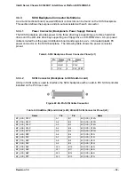
The second connector has 4 pins and is cabled to the 2x3 pin power lead from the power
supply. The power cable for the drive is included in the SC1400UP in the form of a Y power
cable. Both ends of the Y cable are necessary when a slimline CD/DVD is used in conjunction
with a floppy installed in the hard drive bay. Both ends of this are identical and have the
following pinout.
Table 6. 4-pin CD-ROM power connector Pinout (J5)
Pin
Name
1 P12V
2 GND
3 GND
4 P5V


