8
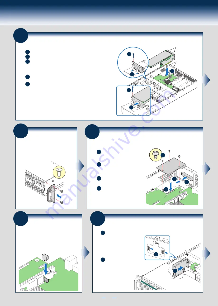
General Installation Process
14
Install Rack Handles
NOTE: Rack handles are required to install the
bezel. For detailed instructions, see the product
Service Guide available on the Intel
®
Server
Deployment & Management DVD.
16
Install Intel® RAID C600
Upgrade Key (optional)
Locate the white 4-pin key header next to Riser Slot 1.
Carefully pickup the Intel
®
RAID C600 Upgrade Key.
Match the Key and connector orientation and press
down to install.
STOR_UPG_KEY
15
Install Intel® I/O Expansion Module
(optional)
A
D
B
Squeeze the sides of the I/O module
bay filler plate, and pull it away from
the chassis back panel.
Fit the front of the module into the
back panel slot and align the I/O
Module over the three stand-offs.
Secure the module with the three
screws as shown.
C
Carefully press down the I/O
module to engage connectors.
I/O Connector
I/O Module
A
B
C
D
NOTE: If included, remember to
install the EMI shield.
13
Install Add-in Card Riser Assembly
A
Slide back the card guide on the air duct.
Pull up the blue plastic pin out of the card guide.
B
C
Position the riser card edge connector over the server board
riser socket and align the two hooks on the back edge of the
riser assembly with the slots on the back of the chassis, then
press straight down into riser socket.
D
Slide forward the card guide to lock in the back edge of the
add-in card.
E
Insert the blue plastic pin into the card guide to secure the
add-in card.
NOTE:
-
Step A, B, D,
and
E
are only needed when a full-length PCI card
is installed on the riser assembly.
- Riser Slot 2 is not functional without having two processors installed.
Hooks (2)
Slots (2)
Add-in Card
D
E
C
A
B
17
Install Intel® RAID Smart Battery (optional)
A
Locate the mounting holes
inside the chassis and
reposition all cables routed
over the fan bulkhead.
Position the battery against
the side wall and through the
opening in the fan bulkhead.
B
Align the tabs on the plastic
battery holder with the
mounting holes in the
chassis and slide the plastic
battery holder toward the
front of the system until
the tabs engage with the
mounting holes.
A
B
Fan Bulkhead
Summary of Contents for R2000GL series
Page 2: ...This page is intentionally left blank...
Page 22: ...G31061 004...


