Intel® Server System M20NTP1UR - System Integration and Service Guide
42
•
Position and align the OCP* mounting bracket to the OCP* bay on the system back panel
•
Carefully insert the left tab of the mounting bracket into the mounting notch on the left edge of
the opening (See Letter “C”).
•
Using a single fastener screw, secure the mounting bracket to the chassis. (See Letter “D”).
7.
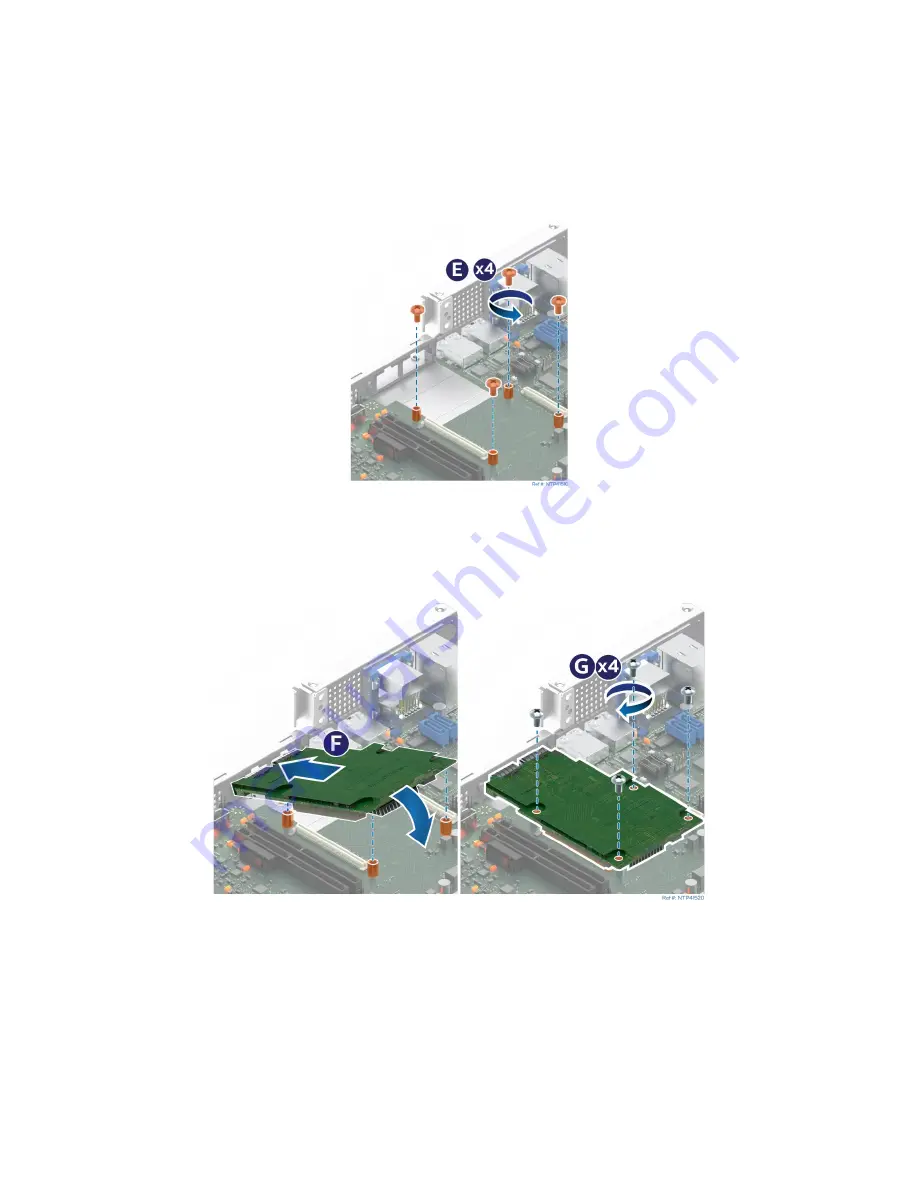
Locate and remove the four screws from the OCP* stand-offs on the server board. (See
Figure 43. OCP* Module Mounting Screws
•
(See Letter “E”)
8.
Mount the OCP* module to the server board (See
Figure 44. OCP* Module Installation
•
Carefully align and insert the cable connectors located on the back edge of the OCP* module
through the opening(s) on the system back panel. (See Letter “F”)
•
Gently lower the OCP* Module until positioned over the four mounting stand-offs
•
Push the OCP* module down onto the server board connector(s) until firmly seated
•
Use 4 screws to secure the OCP* module to the server board (see Letter “G”).
Summary of Contents for M20NTP1UR
Page 2: ...2 This page intentionally left blank...
Page 101: ...Intel Server System M20NTP1UR System Integration and Service Guide 101 1 2 3 4 5...
Page 102: ...Intel Server System M20NTP1UR System Integration and Service Guide 102 1 2 3 4 5 6 1 2 3...
Page 103: ...Intel Server System M20NTP1UR System Integration and Service Guide 103 1 2 3 4 5...
Page 112: ...Intel Server System M20NTP1UR System Integration and Service Guide 112 1 2 3 4 5 ESD 6 1 2 3...
Page 113: ...Intel Server System M20NTP1UR System Integration and Service Guide 113 1 2 3 4 5...


