


3
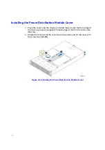
Figure 3. Server Chassis Components
Note:
The blank compute module bay must be covered by a dummy tray cover. When
removed, keep the dummy tray cover properly for future use.
Note:
The compute module bay in the chassis requires either a compute module being
installed and powered up or a dummy tray cover installed to maintain proper
thermal environment for the other running compute modules in the same
chassis. In case of a compute module failure, remove the failed compute module,
and replace with a dummy tray cover until the new compute module is installed.
Label
Description
A
Front control panels
B
Drive bays
C
Power distribution module
D
Power supply modules
E
Hot-swap backplane (attached to the drive cage)
AF006407
LOCK
UNLOCK
B
A
C
D
E