


Case Temperature Reference Metrology
R
86
Thermal/Mechanical Design Guide
D.7
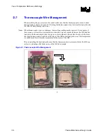
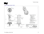
Thermocouple Wire Management
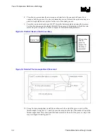
When installing the processor into the socket, make sure that the thermocouple wires exit above
the load plate as shown in Figure 41. Pinching the thermocouple wires between the load plate and
the IHS will likely damage the wires.
Note:
When thermocouple wires are damaged, the resulting reading maybe incorrect. For example, if
there are any cuts into the wires insulation where the wires are pinched between the IHS and the
load plate, the thermocouple wires can get in contact with each other at this location. In that case,
the reported temperature would be at the edge of the IHS/socket load plate area. This temperature
is usually much lower than the temperature at the center of the IHS.
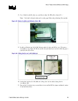
Prior to installing the heatsink, make sure that the thermocouple wires remain below the IHS top
surface, by running a flat blade on top of the IHS for example.
Figure 41. Thermocouple Wire Management
§
Summary of Contents for 640 - Pentium 4 640 3.2GHz 800MHz 2MB Socket 775 CPU
Page 14: ...Introduction R 14 Thermal Mechanical Design Guide ...
Page 38: ...Thermal Management Logic and Thermal Monitor Feature R 38 Thermal Mechanical Design Guide ...
Page 52: ...Intel Thermal Mechanical Reference Design Information R 52 Thermal Mechanical Design Guide ...
Page 60: ...Acoustic Fan Speed Control R 60 Thermal Mechanical Design Guide ...
Page 72: ...Heatsink Clip Load Metrology R 72 Thermal Mechanical Design Guide ...
Page 99: ...Mechanical Drawings R Thermal Mechanical Design Guide 99 Figure 50 Reference Fastener Sheet 1 ...
Page 103: ...Mechanical Drawings R Thermal Mechanical Design Guide 103 Figure 54 Clip Heatsink Assembly ...


