


Intel® Thermal/Mechanical Reference Design Information
R
Thermal/Mechanical Design Guide
51
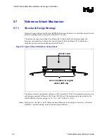
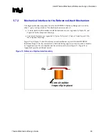
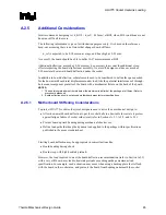
Figure 14. Critical Parameters for Interfacing to Reference Clip
Core
Fin Array
Fan
Clip
See Detail A
Core
Fin Array
Fan
Clip
See Detail A
Detail A
Fin Array
Clip
Core
1.6 mm
Detail A
Fin Array
Clip
Core
1.6 mm
Detail A
Fin Array
Clip
Core
1.6 mm
Detail A
Fin Array
Clip
Core
1.6 mm
Detail A
Fin Array
Clip
Core
1.6 mm
Detail A
Fin Array
Clip
Core
1.6 mm
Figure 15. Critical Core Dimension
R 0.40 mm max
R 0.40 mm max
φ
33.56 +/- 0.10 mm
Gap required to avoid core
surface blemish during clip
assembly. Recommend 0.3
mm min.
1.00 mm min
3.29 +/- 0.10 mm
φ
36.10 +/- 0.30 mm
1.00 +/- 0.10 mm
Core
NOTE: Dimension from the bottom of the clip to the bottom of the
heatsink core (or base) should be met to enable the required
load from the heatsink clip (i.e., 43 lbf n/- 10 lbf)
§
Summary of Contents for 640 - Pentium 4 640 3.2GHz 800MHz 2MB Socket 775 CPU
Page 14: ...Introduction R 14 Thermal Mechanical Design Guide ...
Page 38: ...Thermal Management Logic and Thermal Monitor Feature R 38 Thermal Mechanical Design Guide ...
Page 52: ...Intel Thermal Mechanical Reference Design Information R 52 Thermal Mechanical Design Guide ...
Page 60: ...Acoustic Fan Speed Control R 60 Thermal Mechanical Design Guide ...
Page 72: ...Heatsink Clip Load Metrology R 72 Thermal Mechanical Design Guide ...
Page 99: ...Mechanical Drawings R Thermal Mechanical Design Guide 99 Figure 50 Reference Fastener Sheet 1 ...
Page 103: ...Mechanical Drawings R Thermal Mechanical Design Guide 103 Figure 54 Clip Heatsink Assembly ...


