


Processor Thermal/Mechanical Information
R
20
Thermal/Mechanical Design Guide
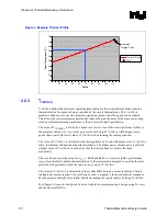
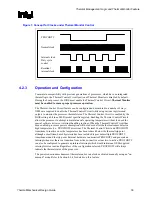
Figure 3. Example Thermal Profile
30
35
40
45
50
55
60
65
70
75
30
40
50
60
70
80
90
100
110
Watts
Ca
se
T
e
mp
e
rat
u
re (
C
)
Thermal Profile
TDP
Heatsink
Design Point
2.2.3 T
CONTROL
T
CONTROL
defines the maximum operating temperature for the on-die thermal diode when the
thermal solution fan speed is being controlled by the on-die thermal diode. The T
CONTROL
parameter defines a very specific processor operating region where fan speed can be reduced.
This allows the system integrator a method to reduce the acoustic noise of the processor cooling
solution, while maintaining compliance to the processor thermal specification.
The value of T
CONTROL
is driven by a number of factors. One of the most significant of these is
the processor idle power. As a result, a processor with a high T
CONTROL
will dissipate more
power than a part with lower value of T
CONTROL
when running the same application.
The value of T
CONTROL
is calculated such that regardless of the individual processor’s T
CONTROL
value, the thermal solution should perform similarly. The higher power of some parts is offset by
a higher value of T
CONTROL
in such a way that they should behave virtually the same
acoustically.
This is achieved in part by using the
Ψ
CA
vs. RPM and RPM vs. Acoustics (dBA) performance
curves from the Intel enabled thermal solution. A thermal solution designed to meet the thermal
profile should perform virtually the same for any value of T
CONTROL
.
The value for T
CONTROL
is calculated by the system BIOS based on values read from a factory
configured processor register. The result can be used to program a fan speed control component.
See the
processor datasheet for further details on reading the register and calculating T
CONTROL
.
See Chapter 6, Acoustic Fan Speed Control, for details on implementing a design using T
CONTROL
and the Thermal Profile.
Summary of Contents for 640 - Pentium 4 640 3.2GHz 800MHz 2MB Socket 775 CPU
Page 14: ...Introduction R 14 Thermal Mechanical Design Guide ...
Page 38: ...Thermal Management Logic and Thermal Monitor Feature R 38 Thermal Mechanical Design Guide ...
Page 52: ...Intel Thermal Mechanical Reference Design Information R 52 Thermal Mechanical Design Guide ...
Page 60: ...Acoustic Fan Speed Control R 60 Thermal Mechanical Design Guide ...
Page 72: ...Heatsink Clip Load Metrology R 72 Thermal Mechanical Design Guide ...
Page 99: ...Mechanical Drawings R Thermal Mechanical Design Guide 99 Figure 50 Reference Fastener Sheet 1 ...
Page 103: ...Mechanical Drawings R Thermal Mechanical Design Guide 103 Figure 54 Clip Heatsink Assembly ...


