background image


Setting Up


CI-3K50601 Project 2191 DMR2731 Rev.1 18-08-11


13

6. 

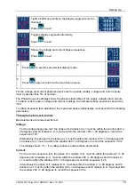
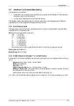
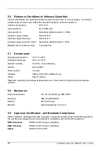
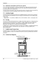
Press 

 to exit the format selection routine.  SET will be 

removed. 


If you have selected 

N2

 format, you can use the 

 or 

 key to select the RS485 

address option and set it as detailed on page 14. 

If you have selected 

ModB

 format, set the serial parameters as follows: 

7. 

Use the 

 or 

 key to cycle through the Baud, parity, 

stop bits and address menu options. 


Baud


Rate (not applicable for JC N2)


8. 

To change the Baud setting, ensure that the display shows the 

Baud setting and press 

 to enter the setting routine.  The 

digits will flash. 


9. 

Use the 

 and 

 keys to select the desired Baud rate 

from the available options: 9600, 4800, 2400, 38.4k (38400) 
and 19.2k (19200). 


10. 

Press 

 to confirm your Baud rate selection. SET will be 

displayed. 


11. 

Press 

 to exit Baud setting routine.  SET will go off and the 

 and 

 keys can be used to select a different Comms 

parameter. 


Parity (not applicable for JC N2)


Note that if parity is set to Odd or Even, Stop Bits will be set to 1 and cannot be changed. 

12. 

Use the 

 and 

 keys to select the Parity option. 


13. 

Press 

 to enter the parity setting routine.  The parameter 

will flash. 


14. 

Use the 

 and 

 keys to select the desired parity option 

from None, Even and Odd. 


Summary of Contents for Ri3

Page 1: ...INTEGRA Ri3 digital metering system DIN Rail Digital Energy Meter for Single and Three phase Electrical Systems Installation and Operating Instructions ...

Page 2: ...t safety information Read them before starting installation or servicing of the equipment Caution Risk of Electric Shock Important safety information is contained in the Maintenance section Familiarise yourself with this information before attempting installation or other procedures ...

Page 3: ... Up 8 4 1 Set up Menu Structure 8 4 2 Set up Entry Methods 9 4 2 1 Menu Option Selection 9 4 2 2 Number Entry Procedure 9 4 3 Change Password 10 4 4 Supply System 10 4 5 dIT Demand Integration Time 11 4 6 CT 11 4 7 RSET Reset 12 4 8 Communications 12 4 9 Pulse Output 15 4 10 Energy Units and 1 Limit 17 4 11 Test 18 4 12 Version Information 20 5 Specification 21 5 1 Measured Parameters 21 5 1 1 Vol...

Page 4: ... 7 Environment 24 5 8 Mechanics 24 5 9 Approval Certification and Standards Compliance 24 6 Maintenance 25 7 Installation 26 7 1 Safety 26 7 2 EMC Installation Requirements 26 7 3 Case Dimensions 27 7 4 Wiring 27 7 4 1 Additional considerations for three wire systems 28 7 5 Auxiliary Supply 28 7 6 Fusing 28 7 7 Earth Ground Connections 28 7 8 Connection Diagrams 28 7 9 RS485 and Modbus or JC N2 Pr...

Page 5: ...powered from the monitored supply where appropriate 1 1 Unit Characteristics The Ri3 can measure and display Line voltages and THD total harmonic distortion of all phases Line frequency Currents current demands and current THD of all phases Power maximum power demand and power factor Active Energy Wh kWh or MWh imported and exported Reactive Energy VArh kVArh or MVArh imported and exported The uni...

Page 6: ...ows a firmware version of 2 510 and a build number of 21 07 Next the unit performs a self test and indicates if the test passes After a short delay the last used measurement screen appears 3 Measurements The buttons operate as follows Selects the Voltage and Frequency display screens In Set up mode this is the Back button Selects the Current display screens In Set up mode this is the Up button Sel...

Page 7: ... set to On Section 4 10 readings below 1 of maximum for the range will be displayed as zero 3 4 Energy Measurements Each successive pressing of the button selects a new range Imported energy in kWh or MWh Exported energy in kWh or MWh Imported reactive energy in kVArh or MVArh Exported reactive energy in kVArh or MVArh This is a two line display that can indicate up to 9999999 9 This example shows...

Page 8: ...e integrated for maximum demand measurement Options are Off 5 8 10 15 20 30 and 60 minutes RSET Resets cumulative Energy and or Demand measurement to zero COMS Communication parameters for RS485 interface FMT Format Modb Modbus protocol Baud rate 2400 4800 9600 19200 38400 Parity none odd even Stop bits 1 1 or 2 if parity is None RS485 network address nnn 3 digit number 1 to 247 Order Norm Rev Ind...

Page 9: ... current layer press to confirm your selection The SET indicator will appear 5 Having completed a parameter setting press to return to a higher menu level The SET indicator will be removed and you will be able to use the and keys for further menu selection 6 On completion of all setting up press repeatedly until the measurement screen is restored 4 2 2 Number Entry Procedure When setting up the un...

Page 10: ...er setting routine and return to the Set up menu SET will be removed 4 4 Supply System Use this section to set the type of power supply being monitored 1 From the Set up menu use the up and down keys to select the System option The screen will show the currently selected supply option 2 Press to enter the Supply Selection routine The current selection will flash 3 Use the up and down keys to selec...

Page 11: ...lection SET indicator will appear 5 Press to exit the dIT selection routine and return to the menu The SET indicator will be removed and you will be returned to the main Set up menu 4 6 CT The CT option sets the maximum primary current 1 to 9999A of the current transformer CT that will give 5A into the meter the maximum 1 From the Set up menu use the up and down keys to select the CT option The sc...

Page 12: ...e Reset routine RSET will clear and you will be returned to the main Set up menu 4 8 Communications The RS485 port can be used for communications using either Modbus or Johnson Controls JC N2 protocol For Modbus parameters such as Baud rate are selected from the front panel whereas for JC N2 they are fixed The RS485 address can be selected for both protocols The first section allows you to select ...

Page 13: ... Baud setting and press to enter the setting routine The digits will flash 9 Use the and keys to select the desired Baud rate from the available options 9600 4800 2400 38 4k 38400 and 19 2k 19200 10 Press to confirm your Baud rate selection SET will be displayed 11 Press to exit Baud setting routine SET will go off and the and keys can be used to select a different Comms parameter Parity not appli...

Page 14: ...lue will flash 19 Use the and keys to select the desired number of Stop Bits 1 or 2 20 Press to confirm your selection SET will be displayed 21 Press to exit Stop Bits setting routine SET will go off and the and keys can be used to select a different Comms parameter RS485 Address An RS485 network can accommodate up to 255 different devices each identified by an address between 1 and 247 Modbus or ...

Page 15: ...a single phase two wire system a CT setting of 900A with a maximum 289V supply implies a maximum energy imported or exported in an hour of 900 x 289 260 kWh which is 72 W seconds A setting of 10Wh per pulse would generate 7 pulses per second Since this exceeds 2 s the unit would not allow such a setting Use this section to set up the relay pulse output Units Import kWh export kWh import kVArh expo...

Page 16: ...ill flash The Rate is the energy that each output pulse represents 9 Use the up and down keys to select the Rate required for the pulse output 10 Press to confirm your selection The SET indicator will appear and the display will stop flashing 11 Press to exit the Rate setting routine The SET indicator will be removed and the and keys can be used to select a different Relay parameter Pulse Duration...

Page 17: ...a To prevent noise from being recorded and causing meter creep a 1 limit can be imposed on the measured input such that energy readings less than 1 of maximum are not recorded This limit can be turned off so that even small energy increments are recorded 1 Use the up and down keys to select the Energy screen 2 Press to select the Energy menu At this stage you can use the and keys to select either ...

Page 18: ... select the Limit screen 8 Press to enter the Limit setting routine The value will flash 9 Use the up and down keys to turn the 1 limit on or off 10 Press to confirm your selection SET will appear and the display will stop flashing 11 Press to exit 1 Limit setting routine SET will be removed 12 Press again to exit the Limit menu and return to the main Set up menu 4 11 Test This option provides var...

Page 19: ...wire mode Measurements are referenced from L1 Voltage For the voltage sequence test the phase of L2 relative to L1 must be within the window 240 48 degrees and L3 relative to L1 must be within the window 120 48 degrees to record the sequence V123 Alternatively the phase of L2 relative to L1 must be within the window 120 48 degrees and L3 relative to L1 must be within the window 240 48 degrees to r...

Page 20: ...se is outside these parameters Current For the current sequence test the phase of I1 relative to L1 L2 must be within the window 330 48 degrees and I2 relative to L1 L2 must be within the window 210 48 degrees and I3 relative to L1 L2 must be within the window 90 48 degrees to record the sequence i123 Alternatively the phase of I1 relative to L1 L2 must be within the window 330 48 degrees and I2 r...

Page 21: ...phase since the last Demand reset Maximum neutral demand current since the last Demand reset three phase supplies only Current THD for each phase 5 1 3 Power and Power Factor Instantaneous power Power 0 to 3600 MW Reactive Power 0 to 3600 MVAr Volt amps 0 to 3600 MVA Maximum demanded power since last Demand reset Power factor 5 1 4 Energy Measurements Imported energy 0 to 9999999 9 Wh kWh or MWh E...

Page 22: ... Power factor 1 of unity 0 01 Active power W 1 of range maximum Reactive power VAr 1 of range maximum Apparent power VA 1 of range maximum Active energy Wh Class 1 IEC 62053 21 Reactive energy VARh 1 of range maximum Total harmonic distortion 1 up to 31st harmonic Temperature co efficient Voltage and current 0 013 C typical Active energy 0 018 C typical Response time to step input 1s typical to 99...

Page 23: ...1 pulse per 0 001 1 Wh VArh 0 01 10 Wh VArh 0 1 100 Wh VArh 1 1 kWh kVArh 10 10 kWh kVArh 100 100 kWh kVArh 1k 1 MWh MVArh 10k 10 MWh MVArh The rate cannot be set to a value that could result in more than 2 pulses per second Pulse width 200 100 60 ms Relay Rating 240V ac 50mA 5 5 2 RS485 Output for Modbus or JC N2 Protocol For Modbus the following RS485 communication parameters can be configured f...

Page 24: ...emperature 10 C to 55 C Storage temperature 20 C to 70 C Relative humidity 0 to 90 non condensing Altitude Up to 2000m Warm up time 1 minute Vibration 10Hz to 50Hz IEC 60068 2 6 2g Shock 30g in 3 planes Maximum operating and storage temperatures are in the context of typical daily and seasonal variation 5 8 Mechanics DIN rail dimensions 72 x 90 mm WxH per DIN 43880 Mounting DIN rail DIN 43880 Seal...

Page 25: ... and safety under fault conditions In normal use little maintenance is needed As appropriate for service conditions isolate from electrical power inspect the unit and remove any dust or other foreign material present Periodically check all connections for freedom from corrosion and screw tightness particularly if vibration is present The front of the case should be wiped with a dry cloth only Use ...

Page 26: ...of an energized current transformer This product should only be operated with the CT secondary connections Earthed If this equipment is used in a manner not specified by the manufacturer protection provided by the equipment may be impaired Auxiliary circuits communication relay outputs are separated from metering inputs and 110 400V auxiliary circuits by at least basic insulation Such auxiliary ci...

Page 27: ...ents such as ferrite absorbers line filters etc if RF fields cause problems It is good practice to install sensitive electronic instruments that are performing critical functions in EMC enclosures that protect against electrical interference causing a disturbance in function 7 3 Case Dimensions I 7 4 Wiring Input connections are made to screw clamp terminals Choice of cable should meet local regul...

Page 28: ...uxiliary supply voltage range Requirements 110 to 400Va c 50 60Hz 10 or 120V to 350Vd c 20 Consumption 3W 7 6 Fusing This unit must be fitted with external fuses in voltage and auxiliary supply lines Voltage input lines must be fused with a quick blow fuse 1A maximum Auxiliary supply lines must be fused with a slow blow fuse rated 1A maximum Choose fuses of a type and with a breaking capacity appr...

Page 29: ...play to check for incorrect wiring of the voltage and current transformer inputs see Section 4 11 The displayed voltage V and current I sequences must be 123 to obtain the correct power voltage and current readings In the event of a voltage phase error e g the same phase connected to two meter inputs the display will show V1 In the event of a current phase error e g a current transformer connected...

Page 30: ...ter slave serial communication protocol with fixed communication parameters Modbus A proprietary communications protocol used for control and monitoring Reactive energy The energy VArh in the reactive component of the supply The current and voltage in the reactive component are mutually 90 out of phase capacitive or inductive resulting in a supply power factor of zero RS485 A serial communication ...

Page 31: ...ncy reading 6 Fuses 28 Hours reset 12 Inputs 21 JC N2 5 12 Johnson Controls 5 12 LED check 19 Limit 17 18 Maintenance 25 Maximum demand 7 Meter creep 17 Meter current 11 Modbus 5 12 23 29 Multiplier 17 Noise 17 Number entry 9 Parity 13 23 Password 10 Phase sequence 19 Power factor 7 Power readings 7 Pulse duration 16 Pulse output 6 15 23 Pulse rate 15 16 Pulse width 15 16 23 Range maximum 22 Reset...

Page 32: ... without notice TE expressly disclaims all implied warranties regarding the information contained herein including but not limited to any implied warranties of merchantability or fitness for a particular purpose The dimensions in this catalog are for reference purposes only and are subject to change without notice Specifications are subject to change without notice Consult TE for the latest dimens...

Reviews: