background image

38

Setup menus

  Menu

 1.Speaker Setup
 2.Input Setup
 3.Listening Mode Setup
 4.Preference
 5.OSD Setup

      |ENTER| Quit:|OSD|

2.Input Setup
     Input:DVD

 1.Audio Setup
 2.Video Setup
 3.Listening Mode Preset 
 4.IntelliVolume
 5.12V trigger
 

     |ENTER|Quit:|SETUP|

Current
Input
Source

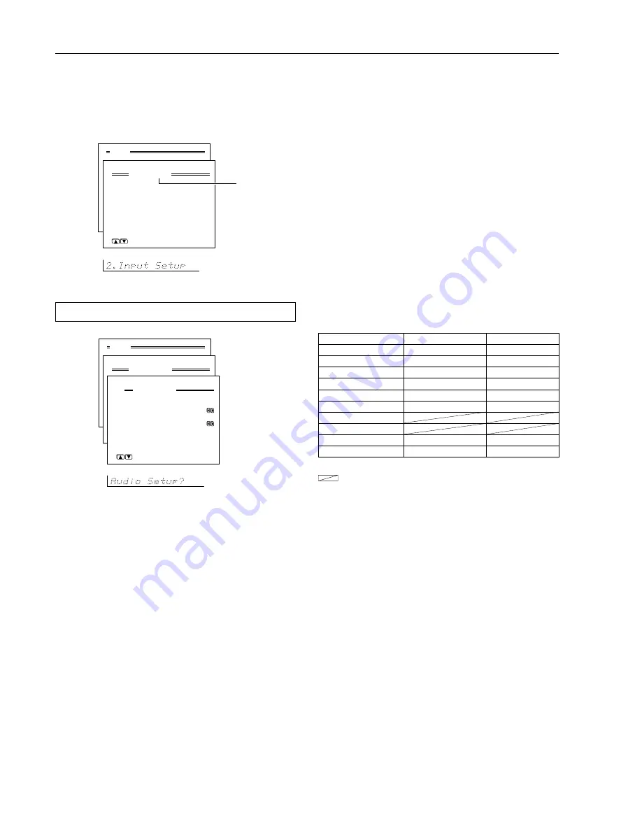
2. Input Setup menu

This menu allows you to setup the various input sources available
with the DTR-6.2. Each input source may have a great number of
settings that are difficult to keep track of, so we recommend making
a chart to record what you have set and for which component to
prevent confusion later.

2-1. Audio Setup sub-menu

----: Available for digital input but not set in initial settings.

 : Not available for digital input.

Initial settings for each input source

Input source

Digital input

Multichannel

DVD

COAX 1

Yes

Video 1

COAX 2

No

Video 2

----

No

Video 3

OPT2

No

Video 4

----

No

Tape

----

No

FM

AM

Phono

----

No

CD

OPT 1

No

  Menu

 1.Speaker Setup
 2.Input Setup
 3.Listening Mode Setup
 4.Preference
 5.OSD Setup

      |ENTER| Quit:|OSD|

2.Input Setup
     Input:DVD

 a.Audio Setup
 b.Video Setup
 c.Listening Mode Preset 
 d.Tone Control
 e.IntelliVolume
 f.12V Trigger 

      |ENTER| Quit:|OSD|

2-1.Audio Setup
     Input:DVD
     Audio:Auto(COAX1)
 
 a.Digital Input:COAX1

 b.Multichannel  :Yes


            Quit:|SETUP|

The settings made in this sub-menu are valid for the input source that
is currently selected with the input source buttons at the front panel
and, therefore, these settings are made separately for each digital
input source. This sub-menu will not appear if the selected input
source button is AM or FM. If this setting is incorrectly made, the
digital audio signals may not be properly output, or not heard at all.

a. Digital Input

This setting tells the DTR-6.2 which input source button on the front
panel is connected with which digital input jack on the rear panel. To
perform this setting, you must first select a digital input source at the
front panel and then set the name of the digital input jack it is
connected to here.
For example, if the input source selected at the front panel is CD and
the compact disc player is connected to DIGITAL INPUT
(OPTICAL) 1, then select “OPT1” here. If the input source selected
is not connected to a digital input, then select “----.”

OPT1:

 Select if connected to DIGITAL INPUT (OPTICAL) 1.

OPT2:

 Select if connected to DIGITAL INPUT (OPTICAL) 2.

COAX1:

 Select if connected to DIGITAL INPUT (COAXIAL) 1.

COAX2:

 Select if connected to DIGITAL INPUT (COAXIAL) 2.

----:

 Select if the input source is not from a digital input jack.

Note:

Do not assign a digital input to more than one input source. If you are
making a digital connection that requires you to change the default
settings, be sure to always first cancel the current digital input setting
and then assign the new setting.

b. Multichannel

This sub-menu will not appear if AM or FM is selected at the front
panel for the input source. The initial settings are “Yes” for the DVD
input source and “No” for all other input sources. This setting is
normally set to “No,” and only needs to be changed to “Yes” if a
DVD player, MPEG decoder, or other component that has a multi
channel port is connected to the MULTI CHANNEL INPUT port for
5.1-channel audio. For example, if a DVD player is connected to the
MULTI CHANNEL INPUT port, then select DVD at the front panel
as the input source, bring up this sub-menu, and select “Yes” for the
Multichannel setting. You can only select Multichannel with the
Audio Selector button when “Yes” is selected here.

Note:

When playing a device that is actually connected to the MULTI
CHANNEL INPUT terminal, select Multichannel with the Audio
Selector button.

Summary of Contents for DTR-6.2

Page 1: ...e unit Following the instructions in this manual will enable you to obtain optimum performance and listening enjoyment from your new AV Receiver Please retain this manual for future reference DTR 6 2 AV Receiver Instruction Manual Appendix 61 Remote controller 46 Setup and operation 24 Before using 2 Facilities and connections 8 ...

Page 2: ...built up static charges Article 810 of the National Electrical Code ANSI NFPA 70 provides in formation with regard to proper grounding of the mast and sup porting structure grounding of the lead in wire to an antenna discharge unit size of grounding conductors location of an tenna discharge unit connection to grounding electrodes and requirements for the grounding electrode See Figure 1 15 Lightni...

Page 3: ... as recommended by the manufacturer 24 Heat The appliance should be situated away from heat sources such as radiators heat registers stoves or other appli ances including amplifiers that produce heat FIGURE 1 EXAMPLE OF ANTENNA GROUNDING AS PER NATIONAL ELECTRICAL CODE ANSI NFPA 70 For U S models Note to CATV system installer This reminder is provided to call the CATV system installer s at tention...

Page 4: ...ing through the Setup menu 35 1 Speaker Setup menu 36 1 1 Speaker Config sub menu 36 1 2 Speaker Distance sub menu 37 1 3 Level Calibration sub menu 37 Facilities and connections Front panel facilities 8 Remote controller 10 Connections 12 Connecting your audio components 13 Connecting your video components 14 Connect to devices with z terminals 16 Cautions regarding the AC OUTLETS connectors 16 C...

Page 5: ... the commands of remote controllers for other devices into the remote controller 54 Programming procedure 54 Erasing the programmed command from one button 56 Erasing all the commands programmed under a MODE button 56 Using a Macro function 57 What is a Macro function 57 Programming a Macro function 57 Running a Macro function 57 Programming the Direct Macro function 58 Running a Direct Macro func...

Page 6: ...dential Unpublished Works 1992 1997 Dolby Laboratories Inc All rights reserved Re Equalization and the Re EQ logo are trademarks of Lucasfilm Ltd Manufactured under license of Lucasfilm Ltd Manufactured under license from Digital Theater Systems Inc US Pat No 5 451 942 and other worldwide patents issues and pending DTS and DTS Digital Surround are trademarks of Digital Theater Systems Inc 1996 Dig...

Page 7: ...ths but this will vary depending on usage 3 2 1 30 30 Using the remote controller Point the remote controller toward the remote control sensor The STANDBY indicator lights up when the unit receives a signal from the remote controller Remote control sensor Standby indicator DTR 6 2 Approx 16 feet Notes Place the unit away from strong light such as direct sunlight or inverted fluorescent light which...

Page 8: ... ADJ Setup Return 1 2 3 7 6 4 5 9 8 0 B C A Front panel facilities See illustration below Here is an explanation of the controls and displays on the front panel of the DTR 6 2 Front panel Front panel display Smart Scan Navigator Dimmer Display Tuning FM Mode Preset Memory Preset Push To Enter DSP Mode ADJ Setup Return E D G I M F H J K L N Rec out indicator Sleep indicator Listening mode or digita...

Page 9: ... Boosts or cuts the treble response Treble adjustment is effective only for the front L R speakers and headphones Front display Remote control sensor 7 Smart Scan Navigator jog dial and indicators 24 26 28 30 31 33 35 45 Used to make settings in the Setup menu change listening mode settings and more Setup button 24 26 35 Press to bring up the Setup menu The OSD menu will appear on the TV monitor a...

Page 10: ...in RETURN button 35 48 For entering the selected setting and returning to the previous menu CH DISC button 28 46 48 52 53 When in the RCVR mode for selecting a tuner preset channel For selecting the disc to be played back for components with disc changers when in the DVD or CD modes CH SEL TOP MENU button CH SEL For selecting the speaker for level adjustment when in the RCVR mode Used together wit...

Page 11: ...and very dark 30 LIGHT button For illuminating the buttons of the remote controller This is button is useful when using the remote controller in dark locations When pressed the buttons on the remote controller light green The button for the mode currently selected lights brighter than the rest MODE MACRO button 57 59 For executing and programming the Macro function SETUP button 35 For displaying a...

Page 12: ...uctions that came with the component that you are connecting Do not plug in the power cord until all connections have been made For input jacks red connectors marked R are used for the right channel white connectors marked L are used for the left channel and yellow connectors marked V are used for video connection Do not bind audio video connection cables with power cords and speaker cables Doing ...

Page 13: ...yer CD Using an RCA type audio connection cable connect the output terminal on the compact disc player to the CD input jacks on the DTR 6 2 Make sure that you properly connect the left channel to the L jack and the right channel to the R jack If the compact disc player has a digital output jack as well be sure to also connect it to either a DIGITAL INPUT COAXIAL or DIGITAL INPUT OPTICAL jack on th...

Page 14: ... audio output Analog audio input Digital audio output Coaxial Digital audio output Coaxial L White R Red L White S video V R Red L White R Red CR PR CB PB Y CR PR CB PB Y Connections Signal flow Audio connection cable Left White Right Red L R Video connection cable S video connection cable Component video connection cable CR PR CB PB Y CR PR CB PB Y Connecting your video components Below is an exa...

Page 15: ...ges 26 38 Using an RCA type audio connection cable connect the audio output terminal on the device to the audio DVD IN jacks on the DTR 6 2 Make sure that you properly connect the left channel to the L jack and the right channel to the R jack If the device has a digital output jack as well be sure to also connect it to either a DIGITAL INPUT COAXIAL or DIGITAL INPUT OPTICAL jack on the DTR 6 2 dep...

Page 16: ...n the standby state all z connected components are also automatically put into the standby state CAUTION If an MD recorder is connected to the TAPE jack on the DTR 6 2 switch the Input Selector from Tape to MD see page 21 REMOTE CONTROL Ex Integra Onkyo CD player Ex Integra Onkyo cassette tape deck DTR 6 2 z connector z connector To connect components using the z terminal simply connect a remote c...

Page 17: ...ound s source and movement Surround Place the left and right Surround speakers 3 feet 1 meter above the listener s ear level and facing toward the sides of the room making sure that the listener is within the speakers dis persion angle These speakers produce the feel of a moving sound while creating the sensation of being in the middle of the action TV or Screen Center speaker Surround right speak...

Page 18: ... Ω slide the IMPEDANCE SELECTOR switch to the right 4 OHMS MIN SPEAKER When you are using only one speaker or when you wish to listen to monaural mono sound a single speaker should never be connected in parallel to both the right and left channel terminals simultaneously To prevent damage to circuitry never short circuit the positive and negative speaker wire Notes The power to the DTR 6 2 must no...

Page 19: ...ctivated for the Preference Powered Zone 2 Setup setting in the Setup menu Note It is important to be aware of the speakerimpedance see previous page When set to Activated the following limitations will be applied so whenever you are not using the remote zone Zone 2 be sure to return the setting to Not Activated You can only use the Stereo and Direct listening modes in the main room When listening...

Page 20: ...ilable IR emitter Connect the mini plug of the IR emitter to the IR OUT terminal on the DTR 6 2 and then place the IR emitter on the remote sensor of the component or facing it When the IR emitter is connected only the signal input to the IR IN terminal is output to the IR OUT terminal The signal input from the remote sensor on the front of the DTR 6 2 will not be output to the IR OUT terminal The...

Page 21: ...unit On the average memory contents are protected over a period of a few weeks after the last time the unit has been turned off This period is shorter when the unit is exposed to a highly humid climate 3 Press the Standby On button to turn on the DTR 6 2 The display and four jog dial indicators will light up and the Standby indicator will turn off If you press the Standby On button again the recei...

Page 22: ...of distortion If the reception is not very clear with the attached FM indoor antenna the use of an outdoor antenna is recommended Connecting the AM loop antenna The AM loop antenna is for indoor use only Set it in the direction and position where you receive the clearest sound Put it as far away as possible from the DTR 6 2 televisions speaker cables and power cords When reception is not satisfact...

Page 23: ...rectional linkage Do not use the same antenna for both FM and TV or VCR reception since the FM and TV or VCR signals can interfere with each other If you must use a common FM TV or VCR antenna use a directional linkage type splitter Connecting an FM outdoor antenna Please make sure that you follow the considerations Keep the antenna away from noise sources neon signs busy roads etc It is dangerous...

Page 24: ...s directly above and below the jog dial are lit turning the jog dial selects a submenu and pushing the jog dial enters the selected submenu i e takes you one level down If the indicators directly to the left and right of the jog dial are lit turning the jog dial changes the setting of the currently selected parameter and pushing the jog dial displays the next parameter Return button Press to go ba...

Page 25: ... DSP Mode ADJ Setup 8 Press the Return button You return to the Speaker Config display 5 Press the jog once and then turn it to set the size of your front speakers Push To Enter DSP Mode ADJ If No is selected for the Subwoofer setting then this setting is fixed to Large Large Select if the front speakers are large sized Small Select if the front speakers are small sized None Select if no center sp...

Page 26: ...lect the connectors to which the source is connected Input 1 or Input 2 8 Press Return repeatedly or press Setup to exit the setting mode Level Calibration submenu This submenu allows you to set the volume levels of each speaker individually so that they all sound at the same level when heard from the listening position If you are continuing from setting the speaker distances and are still in the ...

Page 27: ... the FM Mode button on the front panel The AUTO indication disappears and the radio station is output in the monaural mode To return to stereo press the FM Mode button again AUTO appears Some inter station noise may be heard but the sound will not cut in and out as it would if stereo was selected AUTO TUNED FM STEREO Tuned in stereo Band Frequency Auto mode FM STEREO Lights red The tuner frequency...

Page 28: ...tor lights red Preset Memory Push To Enter DSP Mode ADJ MEMORY MEMORY Lights red Push To Enter DSP Mode ADJ Push To Enter DSP Mode ADJ Selecting a preset radio station 1 Press either the AM or FM input source button The front display should show the currently selected frequency If it displays the listening mode press the Display button to display the frequency 2 Press the Preset button and select ...

Page 29: ...ning off the sound To turn off the sound momentarily such as when interrupted by a phone call press the MUTING button on the remote controller When pressed Muting is displayed on the DTR 6 2 Press the MUTING button again to turn the sound back on Phones Bass Treble HOME THEATER CONTROLLER RC 441M Standby On Standby Power On Off Phones Video 1 Video 3 DVD Video 2 Video 4 Audio Selector Bass Treble ...

Page 30: ...ndividual speaker volumes temporarily follow the procedure given below Each channel can be set between 12 to 12 decibels Note that the calibration settings will return to the original settings when the DTR 6 2 is put in standby 1 Press the CH Level button and select the desired speaker 2 Turn the jog dial to adjust the volume level Display CH Level Push To Enter DSP Mode ADJ When using the remote ...

Page 31: ...ttons on the remote controller Audio Selector Using the tone control To make the BASS and TREBLE dials work for multichannel sources you must first set the tone control to On 1 Turn the tone control on by pressing either the jog dial on the DTR 6 2 or the DIRECT button on the remote controller Master Volume DTR 6 2 Remote controller DTR 6 2 Remote controller DTR 6 2 Remote controller MUTING HOME T...

Page 32: ...sure the Speaker Setup parameters have been set refer to page 24 26 Once the parameters have been set it is not necessary to set them again The outputs for the VIDEO 1 OUT VIDEO 2 OUT TAPE OUT output analog audio signals Do not record from CDs or LDs that support DTS using these outputs If you do the DTS encoded signal will be recorded as noise The 5 1 channel digital surround format has a variety...

Page 33: ...listening mode If pressed the listening mode for the selected input source set in the Listening Mode Preset sub menu is also changed to the All Channel Stereo listening mode DSP Changes the listening mode as shown below Direct Stereo Surround Orchestra Unplugged Studio Mix TV Logic All Ch Stereo Direct If pressed the listening mode for the selected input source set in the Listening Mode Preset sub...

Page 34: ... Speaker Setup 1 Speaker Config 2 Speaker Distance 3 Level Calibration ENTER Quit SETUP Menu 1 Speaker Setup 2 Input Setup 3 Listening Mode Setup 4 Preference 5 OSD Setup ENTER Quit SETUP Setup menus When making the various settings required to configure your DTR 6 2 optimally you can either use the OSD menu that appears on your television monitor or you can use the display on the front of the DTR...

Page 35: ...nu will also be displayed in the front display on the DTR 6 2 The buttons on the remote controller correspond to those on the DTR 6 2 as shown on the right Setup Setup Push To Enter DSP Mode ADJ Push To Enter DSP Mode ADJ Push To Enter DSP Mode ADJ Push To Enter DSP Mode ADJ Push To Enter DSP Mode ADJ Push To Enter DSP Mode ADJ Return 5 Press the RETURN button to return to the previous menu screen...

Page 36: ...or this setting d Surround None Select if no surround left and right speakers are connected Large Select if the surround left and right speakers are large sized Small Select if the surround left and right speakers are small sized If Small is selected for the Front setting then Large cannot be selected for this setting Your speaker settings Tip When setting the speaker size in the Speaker Config su...

Page 37: ... positions due to room designs and configurations These settings and the distance settings performed above are vital to create the proper acoustics required for the optimum sound space and dynamics Notes The speaker level settings here are not effective for multi channel input sources To adjust the speaker levels for multi channel input sources you will need to use the CH SEL LEVEL and LEVEL butto...

Page 38: ...input source button on the front panel is connected with which digital input jack on the rear panel To perform this setting you must first select a digital input source at the front panel and then set the name of the digital input jack it is connected to here For example if the input source selected at the front panel is CD and the compact disc player is connected to DIGITAL INPUT OPTICAL 1 then s...

Page 39: ...PCM then you can set a different listening mode for each This is especially convenient if you frequently play the same types of movies or music See the next page for information regarding the relationship between input sources and listening modes Input source signals a Analog PCM Source Set a listening mode for the input signal from analog sources and PCM sources Note For PCM sources recorded at a...

Page 40: ...l and if that source is quieter than other sources increase its decibel level with the cursor button or if it is louder than other sources decrease its decibel level with the cursor button The IntelliVolume can be adjusted between 12 and 12 decibels Menu 1 Speaker Setup 2 Input Setup 3 Listening Mode Setup 4 Preference 5 OSD Setup ENTER Quit OSD 2 Input Setup Input DVD a Audio Setup b Video Setup ...

Page 41: ...verb effects and the sound loses frame or presence In this case set this setting to Low No reverberation from the DSP will be applied to the sound output from the three front channels so the sound source is be played as it is without any further reverberation Surround Effect You can choose from Low Middle or High This adjusts the reflected and residual noises from the surround left and right speak...

Page 42: ... little effect The Late Night function is effective only on Dolby Digital encoded software This sub menu allows you to set where you will be using the remote controller when you are using it in conjunction with the IR IN terminal i e remote controller signals are input at the IR IN terminal Main Select this when using the DTR 6 2 in the main room If Main is selected at this sub menu to perform ope...

Page 43: ...1 OSD Setup a Background Color Blue1 b Superimpose Mode Normal c Immediate Display On d Display Position Bottom Quit SETUP c Immediate Display On Select this to have the screen immediately display certain operations as you perform them The display will remain for a few seconds after the operation is completed Off Select this to turn off the immediate display of operations Hint If this is set to Of...

Page 44: ...ource button for the source that you want to record Recording the input source REC OUT selector When using the DTR 6 2 to record a source you must select that source to be output from the TAPE OUT jacks Caution Surround and multichannel audio cannot be recorded You cannot perform digital recording with the DTR 6 2 Also digital to analog signal conversion is not possible so to record audio signals ...

Page 45: ...TR 6 2 2 Select a source After pressing the Zone 2 button you must press an input source button within 3 seconds The Zone 2 indicator lights Ex When the CD button is pressed When Zone2Sel Off is displayed the output to the remote zone is turned off Caution If you are not using the system in the remote zone always press the Zone 2 button consecutively to turn the ZONE 2 function off MUTING HOME THE...

Page 46: ...ntrolling an Integra Onkyo cassette tape deck The z connector of the Integra Onkyo cassette tape deck must be connected to the DTR 6 2 see page 16 1 Press the RCVR MODE button The RCVR MODE button lights green 2 Press the desired operation button The buttons shaded in the figure to the left are the operation buttons that can be used to control an Integra Onkyo cassette tape deck Operation buttons ...

Page 47: ... disc player Operation buttons ON Turns on and off the compact disc player same as STDBY button on the remote controller DISC Selects a disc in the CD changer Track down Track up Play Stop Fast reverse Fast forward Pause OPEN CLOSE r Open close the disc tray 0 1 to 9 10 Numeric keys RANDOM R For random playback You may also use the following buttons VOL Adjusts the volume at the DTR 6 2 MUTING Act...

Page 48: ...dly to select an audio and or language track recorded on a DVD Audio Video ANGLE Press repeatedly to select a camera angle when a DVD Video is recorded with multiple angle playback SUBTITLE Press repeatedly to select one of the subtitle languages recorded on a DVD Video SEARCH Press to find the specific section on a disc where you want to start playback RANDOM R Press to start random playback Chap...

Page 49: ... DTR 6 2 MUTING Activates the muting function at the DTR 6 2 MD operation buttons Numeric keys HOME THEATER CONTROLLER RC 441M MD MODE ON STDBY VOL MUTING ENTER Using remote controller SAT CABLE VCR and TV MODE buttons No preset codes are programmed into the SAT CABLE VCR and TV MODE buttons You can use these buttons to program the remote controller signals of other devices There are two methods O...

Page 50: ...ove If it still does not operate properly then program the commands one by one to the buttons on the RC 441M remote controller When entering the code of Integra Onkyo DVD players There are three SETTING numbers Choose the SETTING number according to how you will be using the DVD player No 601 613 These codes are for operating the Integra Onkyo DVD player by pointing the remote controller directly ...

Page 51: ... MIVAR 174 175 NEC 176 177 NOKIA 178 179 180 181 OCEANIC 181 NORDMENDE 182 183 OKANO 152 ORION 184 185 186 PANASONIC 187 188 189 190 PHILIPS 152 162 191 PIONEER 192 193 PROSCAN 194 QUASAR 195 RADIO SHACK 196 RCA 110 141 197 198 199 200 SABA 182 183 201 SAMSUNG 202 203 204 205 206 207 208 SANYO 209 210 211 212 SCHNEIDER 103 SEARS 213 SELECO 214 215 SHARP 216 217 SONY 218 219 220 221 222 223 SYMPHON...

Page 52: ... THEATER CONTROLLER RC 441M ON STDBY MENU ENTER MUTING SAT MODE CH VOL SAT MODE Satellite Tuner Mode 1 Press the SAT MODE button The SAT button lights green 2 Press the desired operation button The buttons shaded in the figure to the left are the operation buttons that can be used to control your satellite tuner unit The buttons given below have operations programmed into them ON Turns on and off ...

Page 53: ...wn the television channels TV VCR Switches the TV VCR input for the television 0 1 to 9 10 Numeric keys ENTER Confirm VOL Adjusts the volume at the television MUTING Activates the muting function at the television VCR MODE VCR Mode 1 Press the VCR MODE button The VCR button lights green 2 Press the desired operation button The buttons shaded in the figure to the left are the operation buttons that...

Page 54: ...ler over to the RC 441M remote controller one at a time Each command is then programmed to a different button on the RC 441M remote controller Any button is programmable for this step except for the eight MODE buttons RCVR CD DVD MD SAT CABLE VCR and TV the two MACRO buttons DIRECT and MODE and the LIGHT button Even after the commands have been memorized keep your old remote controller in a safe p...

Page 55: ...ree times quickly and the remote controller exits the programming mode Resume from Step 2 If a failure occurs during programming the SEND LEARN indicator flashes three times quickly and the remote controller exits the programming mode Resume from Step 3 If a failure occurs five times in row during programming the remote controller exits the programming mode Resume from Step 3 If you try to program...

Page 56: ...e the SEND LEARN indicator flashes three times quickly and the remote controller exits the erasing mode Resume from Step 1 Erasing all the commands programmed under a MODE button 1 Press and hold down the desired MODE button press the ENTER button twice and then release both buttons When you press the MODE button the SEND LEARN indicator lights When you press the ENTER button the lamp turns off Wh...

Page 57: ...ote controller exits the programming mode Resume from Step 1 Running a Macro function Perform the procedure below to run a macro function that you have programmed into the remote controller After programming a macro you should always run it at least once to make sure that it has been programmed properly 1 Point the remote controller at the DTR 6 2 and press the CD MODE button 2 Press the MODE MACR...

Page 58: ...s during the programming the SEND LEARN indicator flashes three times quickly and the remote controller exits the programming mode Resume from Step 1 If you perform an invalid operation during programming the SEND LEARN indicator flashes three times quickly and the remote controller exits the programming mode Resume from Step 1 Running a Direct Macro function Perform the procedure below to run a d...

Page 59: ...rwriting the previous macro with a new macro Erasing a direct macro from the DIRECT MACRO button 1 Press and hold down any one of the eight MODE buttons press the DIRECT MACRO button and then release both buttons When you press the MODE button it lights green and the SEND LEARN indicator lights When you press the DIRECT MACRO button the indicator turns off When you release the buttons the indicato...

Page 60: ... LEARN indicator lights up for about ten seconds and then turns off All programmed commands and macros are erased and the remote controller returns to its factory presets Notes Proceed to Step 3 immediately after Step 2 otherwise the batteries will be consumed quickly If you press any button other than the ENTER button in Step 3 nothing will be erased In this case resume from Step 1 MACRO MODE MOD...

Page 61: ... H D Frequency Response 5 Hz to 100 kHz 1 dB 3 dB RIAA Deviation 20 Hz to 20 kHz 0 8 dB Tone Control Bass 10 dB at 50 Hz Treble 10 dB at 20 kHz Signal to Noise Ratio Stereo Phono 80 dB IHF A 5 mV input CD Tape 100 dB IHF A 0 5 V input Muting 50 dB TUNER SECTION FM Tuning Range 87 5 to 108 0 MHz 50 kHz steps Usable Sensitivity Mono 11 2 dBf 1 0 µV 75 Ω IHF 0 9 µV 75 Ω DIN Stereo 17 2 dBf 2 0 µV 75 ...

Page 62: ...r cord is disconnected Connect power cord External noise in the affecting the internal microcomputer Turn the power button off and then on again or remove the power cord from the outlet and then plug it in again Internal fuse is blown Contact your Integra Onkyo authorized Service Center Power turns on but no sound Muting is displayed Press the MUTING button on the remote controller to turn it off ...

Page 63: ...ot allowed by the current speaker configuration Not available in Zone 2 mode The operation is not allowed because the Zone 2 mode is turned on Only available with Dolby D No setting other than Dolby Digital can be set Not available in this Listening mode This operation cannot be performed in this listening mode Not available with this signal This operation cannot be performed with this input signa...

Page 64: ... Way Upper Saddle River N J 07458 U S A Tel 201 785 2600 Fax 201 785 2650 E mail integra onkyousa com Integra Division of ONKYO CORPORATION Sales Product Planning Div 2 1 Nisshin cho Neyagawa shi OSAKA 572 8540 JAPAN Tel 072 831 8111 Fax 072 833 5222 SN 29343021A ...

Reviews: