Integra DTR-5.4 Instructional Manual Download Page 30

30

Setup Menu

When making the various settings required to configure your DTR-6.4/5.4 for optimum performance, you can either use the OSD Menu that
appears on your television monitor or you can use the display on the front of the DTR-6.4/5.4. The OSD Menu is a settings menu that is
displayed on your TV monitor. For your reference when performing the setting procedures, this manual shows both the OSD Menu displayed
on your television monitor and the display on the front of the DTR-6.4/5.4.
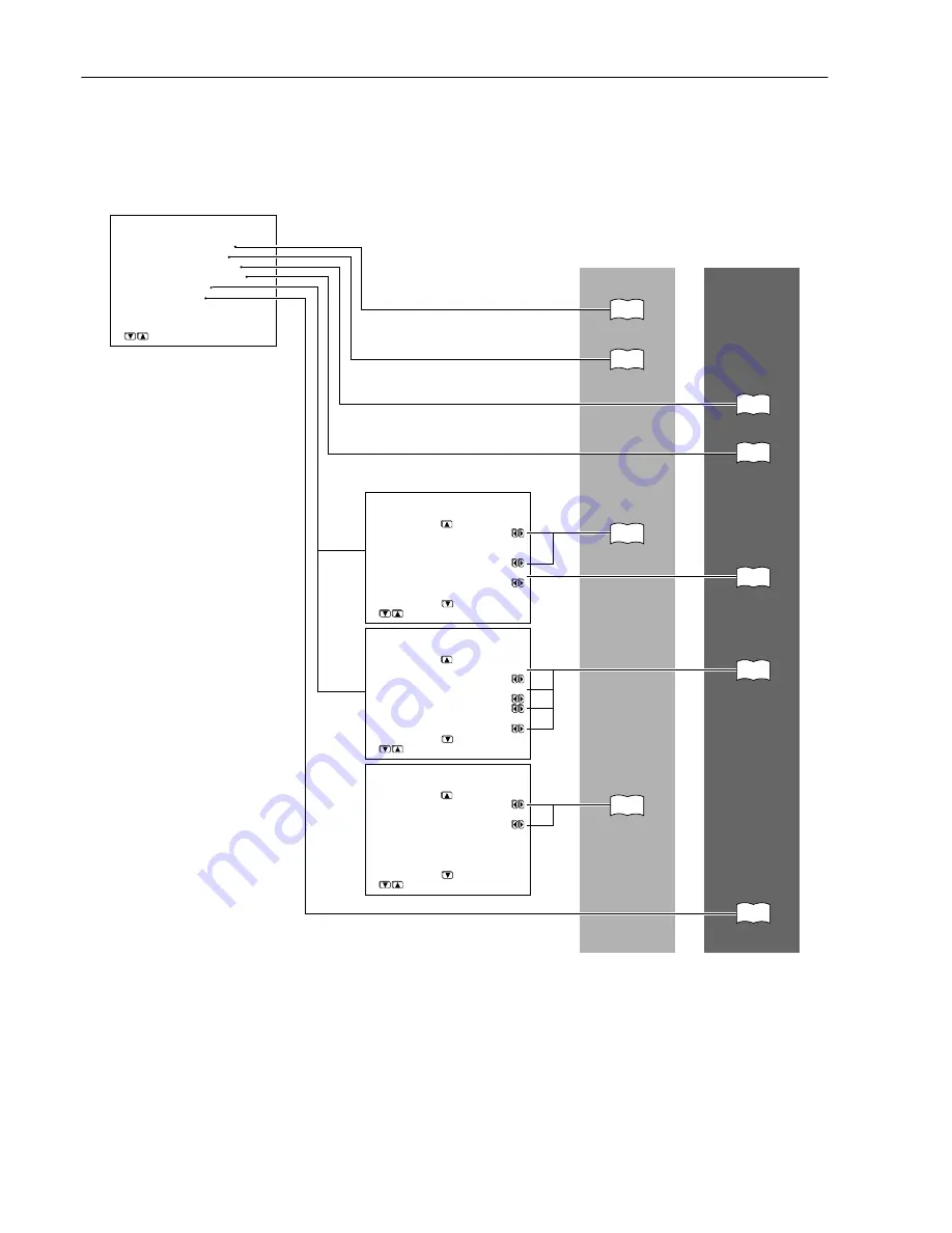
* Menu *****************
 
 1.Hardware Config   
 2.Speaker Config
 3.Speaker Distance
 4.Level Calibration
 5.Input Setup
 6.Preference


5.Input Setup
 ****Input:DVD   *******
 
 a.Digital Input :OPT1  

 b.Component Video
               :Input1
 c.IntelliVolume 
                :  0dB


      Quit:|SETUP|

5.Input Setup
 ****Input:DVD   *******
 
 d.Analog/PCM/D.F.2ch
           :Last Valid
 e.PCM fs=96k
           :Last Valid
 f.D.F.    :Last Valid
 
 g.D.F.Mono:Last Valid

      Quit:|SETUP|

5.Input Setup
 ****Input:DVD   *******
 
 h.12V Trigger A :On     
           
 i.12V Trigger B :Off


      Quit:|SETUP|

|ENTER|Quit:|SETUP|

32

33

52,54

53,55

34

34

56

57

58

Configuring the 

initial settings

Making the 

optimum 

settings

Summary of Contents for DTR-5.4

Page 1: ...he instructions in this manual will enable you to obtain optimum performance and listening enjoyment from your new AV Receiver Please retain this manual for future reference Contents Before using 2 Fa...

Page 2: ...ult and serious damage to the appliance Use only with a cart stand tripod bracket or table recommended by the manufacturer or sold with the appliance Any mounting of the appliance should follow the ma...

Page 3: ...cur in a particular installation If this equipment does cause harmful interference to radio or television reception which can be determined by turning the equipment off and on the user is encouraged t...

Page 4: ...onents 27 Before using Facilities and connections Miscellaneous Connections 28 Connections for remote control 28 RS232 28 A BUS 28 12V TRIGGER OUT 28 Connecting the power 29 Turning on the power 29 Tu...

Page 5: ...set an Integra specific surround mode for your listening mode 60 Settings available when you play monaural signal 61 Settings available when you set Theater Dimensional for your listening mode 61 Usin...

Page 6: ...erformance and pre amplifier performance and operation for both digital and analog domains THX Select receivers also feature proprietary THX technologies which accurately translate film soundtracks fo...

Page 7: ...e Remove dead batteries immediately to avoid damage from corrosion If the remote controller does not operate smoothly remove the old batteries and replace them both with two newAA batteries Connecting...

Page 8: ...8 Index parts and facilities Here is an explanation of the controls and displays on the front panel of the DTR 6 4 5 4 DTR 6 4 Front panel DTR 5 4 Front panel...

Page 9: ...Press to enter the Setup Menu The OSD Menu will appear on the TV monitor as well as the front display on the DTR 6 4 5 4 Return button 31 When in the Setup Menu press to go back one level If pressed...

Page 10: ...nter the mode for adjusting the volume in the remote zone Zone 2 Note The Rec Out and Zone 2 buttons use the same circuit and therefore cannot be used at the same time When Rec Out is selected nothing...

Page 11: ...IGGER IN terminal of a component in the remote zone Zone 2 if one has one ANTENNA 24 25 These jacks are for connecting the FM indoor antenna and AM loop antenna that are supplied with the DTR 6 4 5 4...

Page 12: ...power amplifier PRE OUT FRONT SURR CENTER SURR BACK DTR 6 4 only 23 To use the DTR 6 4 as a preamplifier connect a power amplifier to these jacks AC INLET 7 This connector is for connecting the suppli...

Page 13: ...sing the CH Sel button Operation buttons 62 65 Press to operate other devices connected to the DTR 6 4 5 4 Input Selector buttons 34 36 43 Press to select an input source Same as the input selector bu...

Page 14: ...cted to the PRE OUT terminals on the DTR 6 4 the speakers are used for front left front right center surround left surround right surround back left and surround back right speakers 7 channel surround...

Page 15: ...e signals PR PB providing the best picture quality Some TV manufacturers label their component video inputs differently S video connection cable The video quality is higher than the one using the comp...

Page 16: ...ck speakers to the power amplifier see page 23 for details 2 Set the Hardware Config b Surr Back setting to 2 ch PRE OUT see page 32 Note If you connect the surround back speakers to the power amplifi...

Page 17: ...oofer 3 Front left speaker 4 Center speaker 5 Front right speaker 6 Surround left speaker 7 Surround right speaker 8 Surround back left speaker 9 Surround back right speaker 10 Listening position 10 8...

Page 18: ...player With the initial settings of the DTR 6 4 5 4 the CD input source is set for digital input at the COAXIAL jack If the digital connection is made to a different jack this must be changed at Input...

Page 19: ...puts to make video recordings When connecting a VCR or other video component make sure you connect its audio and video leads to the same bank e g both to VIDEO 3 The VIDEO 4 inputs are located on the...

Page 20: ...or the DIGITAL IN OPTICAL jack of the DTR 6 4 5 4 depending on the type of connector on the DVD player With the initial settings of the DTR 6 4 5 4 the DVD input source is set for digital input at the...

Page 21: ...jacks of the video cassette recorder to the VIDEO 1 OUT audio jacks of the DTR 6 4 5 4 Make sure that you properly connect the left channels to the L jacks and the right channels to the R jacks If you...

Page 22: ...he audio output jacks of the device to the VIDEO 2 IN audio jacks of the DTR 6 4 5 4 and connect the audio input jacks of the device to the VIDEO 2 OUT audio jacks of the DTR 6 4 5 4 Make sure that yo...

Page 23: ...e If you use a power amplifier connected to the SURR BACK PRE OUT terminal and connect two surround back speakers to the amplifier set the Hardware Config b Surr Back setting to 2ch PRE OUT see page 3...

Page 24: ...ust its orientation until the clearest signal is received Fix it with push pins or similar items in the position that will cause the least amount of distortion If the reception is not very clear with...

Page 25: ...na Insulated antenna cable Do not use the same antenna for both FM and TV or VCR reception since the FM and TV or VCR signals can interfere with each other If you must use a common FM TV or VCR antenn...

Page 26: ...or pre main amplifier When completing your connection refer to Enjoying music in the remote zone on page 49 1 Connect the speakers for the remote zone Zone 2 to the ZONE 2 SPEAKERS terminals 2 Set the...

Page 27: ...connection select Zone 2 at Hardware Config IR IN Position see page 32 If the remote controller signal does not reach the DTR 6 4 5 4 remote sensor Connecting block IR Receiver Remote Controller DTR...

Page 28: ...connector Ex Integra Onkyo CD player Ex Onkyo cassette tape deck connector If a component has two terminals you can use either one to connect to the DTR 6 4 5 4 The other one can be used to daisy cha...

Page 29: ...ver returns to standby state Turning on the power Turn off Before you can use the remote controller you must perform step 1 above and place the DTR 6 4 5 4 in the standby state 1 Press the RCVR Mode b...

Page 30: ...isplayed on your television monitor and the display on the front of the DTR 6 4 5 4 Menu 1 Hardware Config 2 Speaker Config 3 Speaker Distance 4 Level Calibration 5 Input Setup 6 Preference 5 Input Se...

Page 31: ...button DOWN lower edge of ENTER button LEFT left edge of ENTER button RIGHT right edge of ENTER button ENTER ENTER RETURN RETURN If you want to perform these operations using the remote controller fir...

Page 32: ...urr In this setting sound will not be output from the Zone 2 speakers which is connected to the ZONE 2 SPEAKERS terminals In the main room 6 1 channel playback will always be available Zone 2 In this...

Page 33: ...d cursor buttons to select Surround L R and then use the and cursor buttons to select the surround speaker setting None Select if no surround left and right speakers are connected Large Select if the...

Page 34: ...nitors like TV to the COMPONENT VIDEO OUTPUT jacks on the DTR 6 4 5 4 Front speaker diameter crosscover frequency Larger than 8 20 cm 60 6 1 2 8 16 20 cm 80 5 1 4 6 1 2 13 16 cm 100 3 1 2 5 1 4 9 13 c...

Page 35: ...Input DVD a Digital Input OPT1 b Component Video Input1 c IntelliVolume 0dB Quit SETUP Menu 1 Speaker Config 2 Speaker Distance 3 Level Calibration 4 Input Setup 5 OSD Setup 6 Preference 5 Input Setup...

Page 36: ...ally after a few seconds If you want to perform these operations using the remote controller first press the RCVR Mode button 1 Press the desired input source The selected source name appears on the d...

Page 37: ...ht and left channels The headphone volume level can be adjusted at the Setup Menu see page 58 Note The signal to the remote zone Zone 2 will not be affected by whether or not headphones are connected...

Page 38: ...d channel When no LFE number is given there is no LFE channel Also if there is no program format for the input signal nothing will be displayed When the input signal is linear PCM The sampling frequen...

Page 39: ...y switch to analog output even though Auto is selected with the Audio Selector button Selecting the type of audio input signal Audio Sel A DTR 6 4 5 4 Remote controller Notes on DTS If you play a DTS...

Page 40: ...me level at the listening position For the front right front left center surround right and surround left speakers the output levels can be adjusted between 12 and 12 decibels The subwoofer can be adj...

Page 41: ...Direct button In either listening modes the DTR 6 4 faithfully reproduces an audio signal bypassing the tone control circuit When you select Pure Audio in the DTR 6 4 the display indication and the p...

Page 42: ...kHz increments for AM You can press the Tuning or button continuously for more than 0 5 seconds to scan for an FM station in the direction of the button you pressed FM auto tuning mode After you rele...

Page 43: ...igned number lights This programs the radio station as a preset radio station Up to 40 stations can be stored in memory as preset radio stations Presetting a radio station MEMORY Lights red Flashes Li...

Page 44: ...hannel output Listening Modes Dolby Digital EX Enabled when playing back sources with surround tracks that were encoded using the Surround EX technology Dialog norm Dialogue Normalization Dialog Norm...

Page 45: ...the stereo image It will simulate the natural reverberation that is created in large halls Unplugged This mode is suitable for acoustical instrumental sounds vocals and jazz music By emphasizing the f...

Page 46: ...te controller Surround SURR Changes the listening mode for the signal type that is currently being input from the selected input source to the surround mode that matches the signal type e g Dolby Pro...

Page 47: ...g Dolby Pro Logic II Dolby Digital DTS or DTS Neo 6 If pressed the corresponding settings in the Input Setup menu for the selected input source is also changed see page 57 All ST remote controller on...

Page 48: ...gital are automatically played back in Dolby Digital EX If the source has no EX flag the source is played back in Dolby Digital On When a Dolby Digital source with an EX flag is input the listening mo...

Page 49: ...will turn off in the remote zone If you select FM or AM with the Tuner input source button when the source for the remote zone Zone 2 is set to AM or FM the output for the remote zone also changes to...

Page 50: ...you change the input source that you are watching or listening to the selected source will be recorded Recording a source different from that you are listening to The DTR 6 4 5 4 allows you to listen...

Page 51: ...if you change the input source that you are watching or listening to the selected source will be recorded Hint You can also record the video from one source and the audio from another source together...

Page 52: ...7ft f Surr Left 7ft g Subwoofer 7ft Quit SETUP 3 Use the and cursor buttons to select Unit and then use the and cursor buttons to select the desired unit of measure feet Select if you will enter the...

Page 53: ...he DTR 6 4 will now emit the pink noise from the front right speaker Calibrating the speaker levels Menu 1 Speaker Config 2 Speaker Distance 3 Level Calibration 4 Input Setup 5 OSD Setup 6 Preference...

Page 54: ...t Front L R and then use the and cursor buttons to set the distance from the front speakers to your normal listening position 5 Use the and cursor buttons to select Center and then use the and cursor...

Page 55: ...other speakers and adjust the volumes until all speakers are adjusted to the same level The pink noise level can be adjusted to anywhere between 12 and 12 decibels for all speakers in 1 decibel incre...

Page 56: ...ct the desired input source 2 Press the Setup button on the front panel or on the remote controller to display the main menu on the monitor and the front display The main menu appears Adjusting the vo...

Page 57: ...ormat but for PCM e PCM fs 96kHz source This sets the listening mode for Digital PCM sources recorded with a sampling rate of 96 kHz f Digital Format source This sets the listening mode for Dolby Digi...

Page 58: ...for OSD such as the display position 1 Display the main menu Press the Setup button on the front panel or the remote controller 2 Use the and cursor buttons to select 6 Preference and then press the E...

Page 59: ...e values mode 4 Press the Audio Adjust button This completes the setting and the menu display disappears Bass 0dB Treble 0dB DTR 6 4 only Bass Separately adjust the bass setting in 2 step increments T...

Page 60: ...channels at half level 6 dB for each channel The signal level sent to the center channel output is not affected by Center Image This control should be set based on room layout and personal preference...

Page 61: ...ensional mode the setting of 20 and 40 degrees are only for nominal purposes so select the setting that is closest to your actual listening angle Center If the speaker system has a center speaker the...

Page 62: ...troller first press the RCVR Mode button to select the DTR 6 4 5 4 and then press the CD Input Selector button 1 Press the RCVR Mode button The RCVR Mode button lights 2 Press the TUN input selector b...

Page 63: ...e use the On button to put the DVD player in the standby state Setup Displays the OSD of the DVD player Moves cursor in the OSD Menu of the DVD player ENTER Enter button for the OSD Menu of the DVD pl...

Page 64: ...CD Mode button The CD Mode button lights 2 Press the desired operation button The buttons shaded in the figure to the left are the operation buttons that can be used to control an Integra Onkyo compa...

Page 65: ...l an Onkyo MD recorder Operation buttons On Turns on and off MD player same as Standby button on the remote controller Track down Track up Play Stop Skip backward Skip forward Rec Record Pause Eject 1...

Page 66: ...program press the Display button and then release both buttons The Send Learn indicator lights when the Mode button is pressed and turns off when the Display button is pressed When the indicator turns...

Page 67: ...356 357 358 359 360 361 362 363 364 NEC 365 366 367 NOKIA 313 NORDMENDE 368 369 370 OKANO 371 372 ORION 319 373 PANASONIC 374 375 376 377 378 PHILIPS 353 379 380 PHONOLA 311 PIONEER 381 RCA 382 SABA...

Page 68: ...figure to the left are the operation buttons that can be used to control your satellite tuner unit The buttons given below have operations programmed into them On Turns on and off satellite tuner unit...

Page 69: ...can be used to control your VCR The buttons given below have operations programmed into them On Turns on and off the VCR same as Standby button on the remote controller CH Changes selected preset cha...

Page 70: ...the RC 534M 517M remote controller one at a time Each command is then programmed to a different button on the RC 534M 517M remote controller Any button is programmable for this step except for the eig...

Page 71: ...e controller and therefore may not be able to be programmed Some remote controllers have a single button that performs multiple functions for example the function may change each time the button is pr...

Page 72: ...xecuted with just one touch Note that for the macro function only one macro can be programmed For example to program the macro described above on this page for the Macro button perform the steps given...

Page 73: ...ns off then the remote controller has exited the erasing mode because either you have made a mistake during erasing or a time out has occurred because no button has been pressed Resume from Step 1 If...

Page 74: ...eble 10 dB at 20 000 Hz Signal to noise ratio stereo Phono 80 dB IHFA 5 mV input Direct mode Line 106 dB IHFA 0 5V input Direct mode Muting 50 dB TUNER SECTION FM Tuning range 87 5 108 0 MHz 50 kHz st...

Page 75: ...gnal to noise ratio stereo CD Tape 106 dB IHFA 0 5V input Muting 50 dB TUNER SECTION FM Tuning range 87 5 108 0 MHz 50 kHz steps Usable sensitivity Mono 11 2 dBf 1 0 V 75 IHF 0 9 V 75 DIN Stereo 17 2...

Page 76: ...e Center setting to Large or Small at Speaker Config see page 33 No sound or very low volume from subwoofer Subwoofer setting is set to No Set the Subwoofer setting to Yes at Speaker Config see page 3...

Page 77: ...TV or monitor is connected to COMPONENT VIDEO OUT connectors see page 19 VIDEO and AUDIO Front panel controls function but remote controller controls do not No batteries in remote controller Insert b...

Page 78: ...because the muting is activated Zone 2 is not On Will not work because the Zone 2 has not been turned on Also refer to the respective instruction manuals of the CD player DVD player video cassette re...

Page 79: ...79 Memo...

Page 80: ...J 07458 U S A Tel 201 785 2600 Fax 201 785 2650 http www integrahometheater com Integra Division of ONKYO CORPORATION Sales Product Planning Div 2 1 Nisshin cho Neyagawa shi OSAKA 572 8540 JAPAN Tel...

Reviews: