Customer Services (858) 578-7887 & (888) GO IN
TEC
IN
TEC
Controls, 12700 Stowe Dr., Suite 1
0
0, Poway, CA 92064
Fax (858) 578-4633 & (888) FX IN
TEC
www.inteccontrols.com
Specification subject to change without notice.
Printed in USA 131119
Polygard® is a registered trademark of MSR
MGC2-12
PolyGard
®
Multi-Point Controller
User Manual - MGC2-12
Page 24
4 Mounting / Electrical Connection
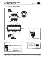
The Controller is installed through the 4 marked mounting holes at the back of the housing. These mounting holes
are accessible after opening the housing. See Fig. 01
The mounting holes should be covered with the enclosed caps after installation.
Please consider the following when selecting the mounting place:
Avoid locations where water, oil etc. may influence proper operation and where mechanical damage might
be possible.
Install cables only from the Topside.
On the left side keep at least 150 mm distance to open the transparent door.
Consider any unusual condition or requirements of the Customer.
Fig. 01
4.1 Electrical Connection
Installation must be done per local electrical codes with the consideration of the technical requirements of the
product.
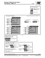
The alarms are available as SPDT, potential free contacts.
For the exact position of the terminations of the relays see the following connection diagram.
8.7 in. (220 mm)
15,2
in.
(3
86mm)

