

2
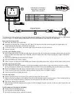
Power Connection Table – CVS100
Color Function
Red
Power (+11 to +32 VDC)
Black Ground
Blue
Reverse Trigger (+11 to +32 VDC)
Green
Source Alarm Out (Functional Only
with Optional Radar Component)
DISPLAY VIDEO OUT/IN
CAMERA
POWER
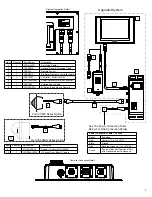
Controller Connection Detail
Upgraded System
1
2
3
4
5
6
7
8
DISPLAY
CVD640LCD
Controller Remote
Display Connection Detail
See The Power Connection Table
Below For Wire Connection Details
10
For CVC400 Series Option
For CVC500AH Series Option
Item Quantity Part
Number
Description
9
1
313-02-02-002
Adapter – Cable to CVC500AH
10
1
CVC500AH(FM)
H Series (Flush Mount) Camera
Item Quantity Part
Number
Description
1 1
CVDxxxLCD Car
Vision
Display
2
1
CVDR5MA
Optional Remote Extension Cable
3 1
CVR100
Remote
Control
4
1
CVDC6MA
Six Meter Display to Controller Cable
5
1
CVS100M
Controller – Molex Version
6
1
CVS100MP3M
Power Harness for Molex Controller
7
1
CVU18M
Existing Coach Cable
8
1
CVC400(FM)
M Series (Flush Mount) Camera
9


