background image

8

1.4 ETHERNET RECEIVER/LAN LOGGER HARDWARE SETUP

1.4 Ethernet Receiver/LAN Logger Hardware Setup

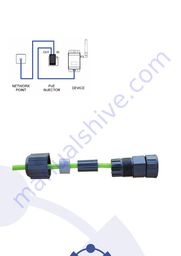
Ethernet receivers and LAN loggers are Power over Ethernet (PoE) devices.  If a PoE plug-in injector is 

supplied, the device should be connected up using Ethernet cables (not supplied) as shown below:

Once connected, turn the device on.

Locate and make a note of the MAC address on the back of the device being installed, this will be 

needed later.

If the device is being used in a location where moisture or dust is present, the supplied waterproof RJ45 

shroud should be fitted over the Ethernet connection.

To fit this, thread the Ethernet cable through the shroud, plug the cable into the device and then screw 

the shroud into the device. 

Summary of Contents for Tinytag Connect

Page 1: ...Tinytag connect User Manual Tinytag Explorer Connect Software Included...

Page 2: ......

Page 3: ...tem Information 2 1 System Components 22 2 2 System Overview 23 2 3 Gateway Configurations 27 2 4 Data Logging 30 2 5 Data Transmission 31 2 6 Alarm E Mails 32 2 7 Exporting Data 33 2 8 Modbus 36 2 9...

Page 4: ...overview of how it works and then specific information on the different types of logger the system supports radio and LAN connected products All users are advised to run the latest version of the Tin...

Page 5: ...Getting Started...

Page 6: ...ound inside the front cover of this manual A Tinytag Connect device Radio receiver loggers and or LAN logger Associated probes and cables Associated power supplies if required You will also need a com...

Page 7: ...rt the installation Review the software s licence agreement and if you accept the terms click I accept the terms in the Licence Agreement then Next You will then be asked where you want to install the...

Page 8: ...ed to all the user accounts on the computer Next click Confirm Code and you will see a message to confirm that the code has been accepted The activation code for Tinytag Explorer can be found on the i...

Page 9: ...Windows you are using you should see a message to say that Windows has detected and is installing a new device When the installation is complete plug the cable into the receiver and turn the receiver...

Page 10: ...s not supplied as shown below Once connected turn the device on Locate and make a note of the MAC address on the back of the device being installed this will be needed later If the device is being use...

Page 11: ...as previously described Browse the Tinytag Explorer CD and locate the LAN folder Run the program VirtualCommPort exe and follow the instructions in the onscreen prompts Run the program IPsetup exe De...

Page 12: ...erial port to COM100 if installing more than one device increment the port number for each successive device used Run the Virtual Comm Port software this is called NB Virtual Comm Port and can be foun...

Page 13: ...LAN LOGGER SOFTWARE SETUP In the Remote host name port fields type the IP address of the Ethernet device and the Listening network port number as previously determined and click Add and Apply The dev...

Page 14: ...ceiver or logger plugged into the computer or network start Tinytag Explorer and go to Options and Communication Options Next click on the Tinytag Connect tab and select Use a Tinytag Connect Product...

Page 15: ...s when user defined logger alarm limits are exceeded the user account that the system is working on must have a properly configured e mail account for this to work To set the address e mails are sent...

Page 16: ...ery time the computer is started recommended check the Autostart gateway service when this computer is switched on box This will automatically start the gateway service running and maintain the networ...

Page 17: ...the same network To connect to an existing system from another computer install Tinytag Explorer on the remote computer and go to Options and Communication Options Select the Tinytag Connect tab Use a...

Page 18: ...Panel On the Tinytag Explorer Connect toolbar you will now see a new drop down menu Select the Tinytag Connect Gateway option A navigation panel will then appear on the left hand side of the screen an...

Page 19: ...then start to flash green In most cases loggers will find their place in the network and be listed in the navigation pane in Tinytag Explorer within a few minutes but depending on the size and complex...

Page 20: ...lect an option from the menu that appears Configure Use this to change a device s settings Get Data Use this to view data from a device Current Readings Use this to view what a device is currently rea...

Page 21: ...and its battery status The table below is a guide to what these icons mean Radio LAN Status Good Communications Solid Radio Waves Flashing Flashing Flashing Solid Flashing Flashing Downloading Data A...

Page 22: ...20...

Page 23: ...System Information...

Page 24: ...ponents used in the Tinytag Connect system that you will see in various places throughout this manual Tinytag Radio Logger Tinytag Explorer Connect Server LAN Connection LAN Data Logger Tinytag Connec...

Page 25: ...llection of data from the loggers the Tinytag Explorer Connect software which allows users to view the data and configure their loggers and the data loggers themselves additionally in radio systems a...

Page 26: ...on a PC if required in this instance the computer ideally needs to be left running continuously Master Connect Gateways can also be installed on stand alone computers if required using a USB radio re...

Page 27: ...ct Gateway Service Tinytag Explorer Connect also has a navigation pane that shows the status of individual data loggers allowing users to see at a glance the status of their system and whether there a...

Page 28: ...h network The advantage of a mesh network is that it is robust and can route data around obstacles For more information on mesh network behaviour see section 3 6 Mesh Network Behaviour LAN loggers con...

Page 29: ...hat are all connected on the same company LAN For example a company may have three sites a head office and two satellite sites and monitoring is required at all three In this example it is preferable...

Page 30: ...up regularly making the system more robust Dedicated Computer Basically the same as the Server configuration but with the Master Gateway running on a computer This configuration might be used when on...

Page 31: ...will be a delay in displaying new measurements due to the need to collect the saved data when the system is restored If a Connect Gateway is shut down it will determine what data a logger holds that...

Page 32: ...e not affected in any way by the time zone of the user who installed or configured the data logger Current Readings If a logger has a good connection with the Connect Gateway live readings will be sho...

Page 33: ...it requests a retransmission to cover the gap If the Connect Gateway is aware of a gap in the data from a logger when it is viewed in Tinytag Explorer then it will ask the user whether they want to se...

Page 34: ...m If an alarm is configured the logger samples the parameter every few seconds If an alarm value is exceeded an alarm indicator will be transmitted to the Connect Gateway immediately and this will sho...

Page 35: ...eway provides access to historic logged measurements for third party software by downloading CSV files over http The URLs for these files are listed on the Connect Gateway interface page and there is...

Page 36: ...the first two columns for example Serial and Next Restart A blank line Two rows of titles for measurement columns For example Maximum and Temperature For loggers that do not support maximum and minim...

Page 37: ...ving measurements from the logger Exporting Incremental Data The CSV files linked from the Exports page will always create a file containing every measurement which is inefficient and cumbersome for s...

Page 38: ...vice detail pages is a link labelled Modbus Registers which links to a page showing Which logger properties are exposed as Modbus registers Which Modbus address is used for each property How many Modb...

Page 39: ...was refreshed from the device Some properties are refreshed daily others are never refreshed Properties containing current measurements are updated every time a measurement is received from the devic...

Page 40: ...eway enforces a limit of no more than 4 concurrent Modbus TCP connections There is no additional limit to concurrent Modbus transactions TCP connections are closed after being idle for 10 seconds Mods...

Page 41: ...logger recording and transmitting if the computer running the system is also affected by the power cut the loggers will record data locally until the problem is resolved the data will then be transmi...

Page 42: ...ng range is required lithium battery versions of the Plus Radio products can be supplied Mains Power Mains powered Tinytag devices should only be used with Tinytag power supplies Ultra Radio loggers a...

Page 43: ...arily depends on the number of radio messages that a logger will hear Battery life will be slightly shorter if A network has a large number of loggers Loggers are set to record at a fast logging inter...

Page 44: ...f this manual for details on how to get the service running again Note that this indicator shows Connected as soon as Tinytag Explorer has connected to the Connect Gateway This does not indicate that...

Page 45: ...Radio...

Page 46: ...may be reduced Indoors the range is quite variable It is usually reduced to between 30 and 80 of full range However it will sometimes be increased maybe up to double the nominal range due to reflectio...

Page 47: ...he antenna Ultra Radio products can be wall mounted or placed flat on a surface such as a shelf or a table top They should be oriented as shown below and not with the logger and antenna both mounted v...

Page 48: ...helf The logger s back plate has mounting holes as shown Ultra Radio Mounting Bracket If wall mounting an Ultra Radio data logger remove the two indicated screws from the rear of the logger and use th...

Page 49: ...avigation pane If working correctly the receiver should be listing in Tinytag Explorer within a few minutes Do all of this before powering up any loggers Nearby Loggers Next The first loggers to be sw...

Page 50: ...ger it is better to be patient and give the system some time If a logger hasn t signed in after a couple of hours that would be the time to try rebooting the unit or moving it to another location Tran...

Page 51: ...ransmit its information to the receiver via another device The mesh will adapt to moving obstacles it is self healing 2 Low set up costs In general it is possible to deploy loggers in an application a...

Page 52: ...s will allow it to form a more effective mesh The number of redundant routing options is a key parameter that will be discussed later 2 All devices can be reconfigured remotely This is possible becaus...

Page 53: ...ultiple Receivers Multiple receivers can provide Redundancy The radio system will continue to function if one receiver fails Range Consider a radio system covering two warehouses but the radio link be...

Page 54: ...e computer has shut down will continue to maintain the mesh network centred on that receiver This ensures that the mesh is ready for use as soon as the computer running the Connect Gateway reboots A r...

Page 55: ...thin direct range This again assumes that there is a well established mesh in particular that the receiver is not just being switched on at the same time Switching On the Receiver Receivers need to fi...

Page 56: ...ESH NETWORK BEHAVIOUR a Good plenty of redundant routing options for all devices b Not Good the red logger has only one place to send its data so everything upstream of there to the right will not be...

Page 57: ...and therefore the reliability of the communications In some cases it can be beneficial to add or move a device to improve redundancy 1 If there is a radio restriction for example a narrow doorway thro...

Page 58: ...uce range to increase battery life but probably not worth it 20 Reducing range by adjusting sensitivity then transmit power will increase battery life and can help if the system will not form a robust...

Page 59: ...e performance of your radio network We therefore advise that you only use this feature following the advice of Tinytag Technical Support Receive Sensitivity The primary parameter to affect radio perfo...

Page 60: ...not be a problem Note that this figure is a typical measurement and not a guaranteed minimum It may be affected by many factors including the surrounding physical environment buildings equipment etc o...

Page 61: ...is one minute Note that this parameter is different from the Measurement Interval which can be controlled using Tinytag Explorer and is typically set to 10 minutes Under normal circumstances measureme...

Page 62: ...evice has not yet established its place in the mesh network c An alarm indicator is signalled Check the nature of the problem using Tinytag Explorer n a Green flash every 4 seconds The device is power...

Page 63: ...Ethernet LAN...

Page 64: ...62 4 1 MOUNTING POINTS 4 1 Mounting Points LAN loggers can be wall mounted or placed on its back on a flat surface such as a shelf The logger s back plate has mounting holes as shown...

Page 65: ...g the alarm at the logger does not acknowledge or switch of the alarm in Tinytag Explorer Connect Cable Wiring An output cable for the external connection is available part number CAB 0042 This is a p...

Page 66: ...AGES Maximum current through any pin 200mA Maximum voltage on the Signal output relative to Ground 30V Protection Both the Power brown and Signal white outputs are protected with a 350mA nominal self...

Page 67: ...er n a Green flash every 4 seconds The device is powered on and does not have any problems Press and briefly hold the Green indicator shows for one The device has been mute button second It then brief...

Page 68: ...ally 30Mb for programs allow up to 100Mb for data The service stores a small amount of configuration information in the Windows Registry in HKEY_LOCAL_MACHINE Software Tinytag Kola Cached measurement...

Page 69: ...www tinytag info software c Regulatory Compliance For the specific standards our radio Ethernet LAN products comply with please see individual product data sheets Changes or modifications not expressl...

Page 70: ......

Page 71: ......

Page 72: ...Intab Interface Teknik AB Gjutarev gen 1 443 61 Stenkullen SWEDEN T 46 0 302 246 00 E info intab se www intab se 9800 0150 ISSUE 2 9th June 2017...

Reviews: