


EloStar Master 3X0 / 4X0 / - smart
Assembly
Manual V.1.03H
43
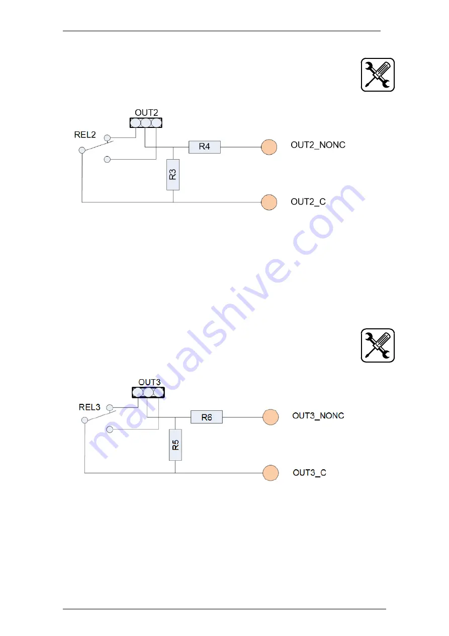
5.6.6
Connecting the Lock Status Contact of EloXT II
The information on the status of the locks remains in the system even after
a power breakdown (bi-stable relay).
The Status contact is closed via terminals 9 and 10 of blocking device
EloXT II with the lock closed.
Fig. 30: Circuit lock status contact
•
Sever the wire of jumper R3 with a screw driver. See page 23.
•
Connect the status contact professionally and according to your demands.
You have successfully connected the Status contact of EloXT II.
5.6.7
Connecting the Door-Open-Alarm-Contact of EloXT II
Not evaluated by UL. The door-open-alarm-contact (output) is connected via
terminals 7 and 8. If configured, the door-open-alarm is triggered after the
selected period of time expires. It remains active until the lock is closed.
.
Fig. 31: Door open alarm contact
•
Sever the wire of jumper R5 with a screw driver. See page 23.
•
Connect the door alarm contact professionally and according to your demands.
You have successfully connected the door-open-alarm-contact of EloXT II.


