OMNIA
+
LEVEL
Smart Deadbolt with Plate
(Stainless Steel)
Instructions/Template for Single Cylinder
Tools Needed:
Doors Prepared with 2
1
/
8
” Cutout
1
- No.1 and No.2 Phillips screwdrivers
2
- Measuring device
3
- Flathead screwdriver
4
- Pliers or hacksaw
5
- Metal file
800-310-7960
/
www.OMNIAindustries.com
Parts Enclosed:
A
- Tailpiece Cylinder with Studs
B
- Cylinder Collar
C
- Exterior Backplate
D
- Mounting Plate for Cylinder
E
- 2 – 2” Cylinder Mounting
Screws
F
- Inside Backplate
G
- 2 – 1
3
/
4
” Mounting Screws
for Inside Backplate
H
- Level Strike
I
- 2 – 1
1
/
2
” Mounting Screws
for Level Strike
J
- Level Battery Cap
K
- CR2 Battery
L
- Level Deadbolt
M
- Level Deadbolt Housing
N
- Hub of Level Bolt
O
- Tubular Latch
P
- Tubular Latch Faceplate
Q
- Tubular Latch Strike
R
- Tubular Latch Dust Box
S
- 2 – 1” Mounting Screws for
Tubular Latch Faceplate
T
- Spindle (Tear drop groove
positioned towards set screw)
U
- 2 Levers
V
- 2 – 1” Mounting Screws for
Level Deadbolt Faceplate
W
- 2 – 1” Mounting Screws for
Tubular Latch Strike
X
- 2 – Set Screws
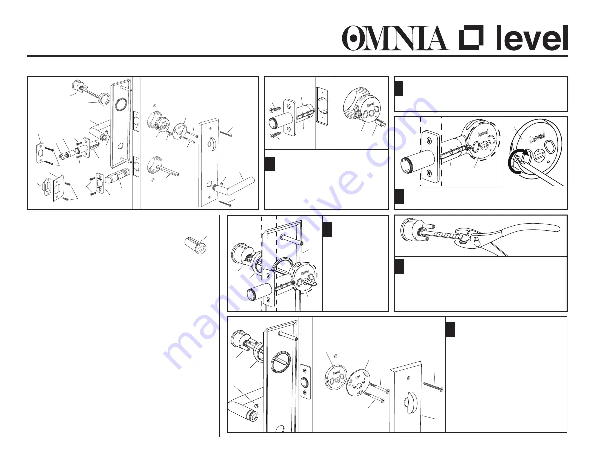
N
Adjust backset on
L
for door, 2
3
/
8
”
(S) or 2
3
/
4
” (L). Insert
L
through
edge of door deadbolt hole and
fasten to door with
V
wood
screws. Insert
M
into 2
1
/
8
” bore
and fit
N
into
M
.
1
Slide
A
through
B
and
C
and
then insert end of
tailpiece into hub
of
M
. Test fit length
of tailpiece into
F
on other side of
door to determine
where to trim the
tailpiece.
4
Trim the appropriate amount of length from tailpiece
using either a hacksaw or break with a pair of pliers.
The tailpiece may need to be filed down to assure proper
movement of the Level bolt when used electronically.
(May work manually, but not electronically. Tailpiece
may be too long.) Remove studs on cylinder, if required.
5
O+L- DBw/PlateSS 0522
In lower hole on door edge, install latch and faceplate
and insert spindle through latch hub (Not Shown).
Follow latchset instruction sheet provided separately.
While
M
is inside of 2
1
/
8
” bore, attach
L
to
M
using screw already assembled to body of
M
.
3
L
M
M
2
M
N
(L)
V
V
L
(S)
B
A
M
C
B
A
C
M
F
G
X
A
B
C
G
F
T
I
N
H
J
K
L
P
O
M
U
G
U
S
R
W
Q
V
V
X
X
E
E
D
Slide
A
through
B
and
C
and then
slide tailpiece through hub of
M
and large hole of
D
. The lever attached
to the backplate needs to slide onto
the spindle in hole below. From interior
side, insert the two
E
screws through
D
and
M
and tighten into
A
. Attach
F
so that the tailpiece slides into the
turnpiece and the spindle below slides
into the lever attached to the backplate.
Fasten at both ends of backplate using
G
screws. On both sides of door, secure
levers with set screw
X
.
6
E
E
D


