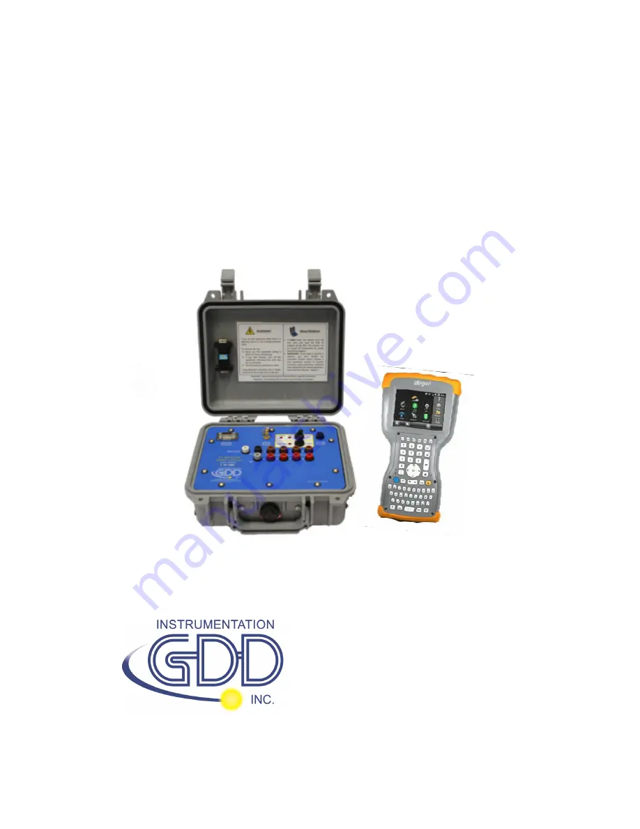
Instrumentation GDD GRx8mini Instruction Manual Download Page 1


IP RECEIVER 


Model GRx8mini 


Instruction Manual 


860 boul. de la Chaudière, suite 200  


Québec (QC), Canada, G1X 4B7 


Tel.: +1 (418) 877-4249   


Fax: +1 (418) 877-4054 


E-Mail: [email protected] 


Web site: www.gdd.ca 


Summary of Contents for GRx8mini

Page 1: ...IP RECEIVER Model GRx8mini Instruction Manual 860 boul de la Chaudi re suite 200 Qu bec QC Canada G1X 4B7 Tel 1 418 877 4249 Fax 1 418 877 4054 E Mail gdd gdd ca Web site www gdd ca...

Page 2: ...nstrumentation GDD Inc 2018 04 06 Page 2 Visit our web site at www gdd ca To Discover GDD s new products Download the latest version of the Instruction Manual Comment on or ask questions about product...

Page 3: ...ignal Processing Options 43 8 2 4 Battery type 44 8 2 5 Open Port 45 8 3 Show option 47 8 3 1 Hotkeys 47 8 3 2 Pseudosection 48 8 3 3 Signal 50 8 3 3 1 Tools menu 52 8 3 3 1 1 Auto Correction 52 8 3 3...

Page 4: ...tallation and settings 78 9 2 2 Establishing connection with a desktop PC 79 9 2 3 Transferring file s from the Allegro2 to a desktop PC 80 9 3 USB connection 82 10 Bluetooth configuration 84 11 GDD R...

Page 5: ...in defining the IP decay curve User modes available Arithmetic logarithmic semi logarithmic Cole Cole and user defined IP display Chargeability values Apparent Resistivity IP decay curves and pseudose...

Page 6: ...ed banana connectors I 1x Standard serial communication cable J 1x Rugged serial communication cable Amphenol connector K 2x Micro USB Communication Cables L 1x External GPS antenna SMA connector M 1x...

Page 7: ...Instrumentation GDD Inc 2018 04 06 Page 7 A B C D F G H I J K L M optional N O P Q E...

Page 8: ...nector is used to connect the serial communication cable between the Allegro2 and the GRx8mini B GPS Connector This connector is used to connect an external GPS antenna SMA C CABLE WIRELESS switch Thi...

Page 9: ...ectrodes In dipole configuration the reference terminal is the first electrode in differential with the second electrode H NUMBERED terminals These terminals are referenced to the Ref terminal Ref is...

Page 10: ...ver channels to keep the Pelican case closed while taking the readings An optional cable mount connector 14 pos can be purchased and used with the instrument K RS 232 external Connector This connector...

Page 11: ...d by GDD Connecting other charger or external batteries using this connector could damage the batteries and the receiver Do not replace the receiver s internal batteries without authorization and advi...

Page 12: ...the receiver at 40 charge Store the receiver in a cool dry place If stored for several months check the battery charge level every six months and recharge them to 50 if they are below 30 charge Never...

Page 13: ...he communication mode using the CABLE WIRELESS switch on the GRx8mini panel In CABLE mode the red light will turn ON only when the GRx8mini software is active 4 Connect the rugged serial communication...

Page 14: ...edure press F5 button You have to start the first acquisition normally before being able to use F5 for the next acquisitions Using F5 will skip all configuration and contact resistance windows If F1 t...

Page 15: ...ent etc for Tx and Rx Click OK or press Enter keystroke to continue 12 Verify if the positions are correct and click OK or press Enter keystroke to continue Displacement enabled Go to previous station...

Page 16: ...are normal click OK or press ESC keystroke to close the window 14 Click NEXT or press Enter keystroke to continue Note If all stations show an INFINITE contact the reference electrode might be discon...

Page 17: ...er P can be displayed alternatively in the Rx main screen under the TOOLS and STOP START buttons To switch from one information to the other use the following shortcut Key V or click on the text label...

Page 18: ...using the optional GDD RTE01 communication box refer to section 8 2 5 to collect live information broadcasted by the GDD Tx4 IP transmitter this menu will show additional Tx current options to choose...

Page 19: ...ompleted in order to correct or revise the coordinates before saving the reading to the file It should not be used to pre set the next reading If the REDO POSITIONS option is checked enter the transmi...

Page 20: ...ad of the Allegro to compare your current data with that of your previous acquisitions Use the Up and Down arrows to see all the channels By clicking on Start the program will automatically come back...

Page 21: ...mmunication mode to use the GRx8mini with a serial communication cable 2 Select the BLUETOOTH communication mode to use the GRx8mini with a wireless connection 3 The following screen appears and you a...

Page 22: ...ation RS 232 cable between the Allegro2 field computer and the GRx8mini to prevent malfunction of the Bluetooth communication and to maximize the battery charge When using the GRx8 32 receiver during...

Page 23: ...number and position Transmitter and receiver position Signal timing Mode GPS time synchronization Special Use the SPECIAL option to Reinitialize the GRx8mini Test the GRx8mini with the internal simula...

Page 24: ...graph Vp and Cycle synchronization graph Decay curve Windows chargeability SP self potential Raw Data Use Raw Data option to Check GPS Start recording a Binary Data file bdf Memory Use the MEMORY opti...

Page 25: ...ls Config Setup The following window appears 2 Select the electrode arrays configuration Dipole Dipole 1 32 Dipole Dipole 2 4 Dipole Dipole 2 16 Dipole Dipole 4 8 Pole Dipole 1 32 Pole Dipole 2 4 Pole...

Page 26: ...c 2018 04 06 Page 26 3 Check the active channel s Tap on the checkbox to select all channels or tap on the checkbox to unselect all channels 4 Select the trigger channel this channel is used for the s...

Page 27: ...the receiver position the separation the transmitter movement offset and the receiver movement offset 1 Select Tools Config Position The following screen appears 2 Enter the line number and select th...

Page 28: ...28 4 Enter the separation between the electrodes of the receiver A negative number is used to define South and West 5 Enter the moving distance of the transmitter and receiver electrodes A negative n...

Page 29: ...nc 2018 04 06 Page 29 8 1 3 Windows Use the WINDOWS option to set the signal timing and the mode 1 Select Tools Config Windows The following screen appears 2 Select the maximum number of stacks 3 Sele...

Page 30: ...lect the mode windows time definition Arithmetic Windows 20 Delay ms 240 Timing ms 2000 80 80 80 80 80 80 80 80 80 80 80 80 80 80 80 80 80 80 80 80 Semi logarithmic Windows 20 Delay ms 40 Timing ms 20...

Page 31: ...rumentation GDD Inc 2018 04 06 Page 31 Windows 4 Delay ms 160 Timing ms 2000 120 220 420 820 Cole Windows 20 Delay ms 20 Timing ms 2000 20 30 30 30 40 40 50 60 70 80 90 100 110 120 130 140 150 160 180...

Page 32: ...settings you have previously saved or you can create new settings Click YES to load your settings from a previously saved file This window will appear In this dialog box select your file The Windows w...

Page 33: ...want to save your file Then click SAVE The User defined settings will be saved so you can reload them into the Allegro2 field PC later OR Click NO if you do not want to save your User defined setting...

Page 34: ...r newer versions Your transmitter itself or linked to another unit must be synchronized with a GPS 1 Refer to Section 8 4 to verify if a satellite is being tracked by the GPS module of your receiver 2...

Page 35: ...ion process you can verify if your receiver is still synchronized with GPS see Section 8 4 to know how to verify the GPS signal GPS well synchronized If you checked Use GPS Time synchronization and if...

Page 36: ...th the ground signal Note that the data acquired with the GPS synchronization can be more accurate than those acquired with the ground signal especially over noisy environment IMPORTANT During the acq...

Page 37: ...hannel and GPS if the receiver is synchronized with the GPS time IMPORTANT Even if the file indicates that your receiver is synchronized with the GPS time it does not confirm that your receiver is wel...

Page 38: ...Tools Special Reinit 2 Click YES to reinitialize the GRx8mini WARNING Please ensure your MEM number is the same than before having reinitialized your GRx8mini If MEM displays a 0 value you may need to...

Page 39: ...ption is used to perform a self test with the internal waveform generator you need to select the Pole Pole configuration to use this option 1 Short the SELF TEST terminal with the channel s you want t...

Page 40: ...Instrumentation GDD Inc 2018 04 06 Page 40 2 Turn ON the receiver 3 Select Tools Config Setup 4 The following screens appear 5 Select the Pole Pole array configuration...

Page 41: ...2018 04 06 Page 41 6 Check the channel s you want to test Click Ok 7 Select Tools Special Simulation 8 Enter the waveform timing default 2000ms 9 Enter the primary voltage default 500mV 10 Enter the...

Page 42: ...internal waveform generator Go to Simulation window and enter 0mV in the Voltage field If you keep the default settings you should obtain the following results for all channels Vp 500mV M 0 000 When...

Page 43: ...tings When offset and gains are applied the signal to noise ratio is improved 1 Select TOOLS Special Signal Processing Options 2 Check the checkboxes of the settings you want to disable and click CONF...

Page 44: ...er automatically If a battery type is detected the information will appear in the About pop up window Select Tools About If the GDD Rx program cannot detect the battery type older Rx firmware versions...

Page 45: ...Rx program and you do not need to set it manually If you select the wrong battery type the battery level indicated in the main window of the GDD Rx program will be slightly different from the actual...

Page 46: ...Instrumentation GDD Inc 2018 04 06 Page 46 If the GDD RTE01 box is not connected or defective the following message will pop up...

Page 47: ...nu 1 Select Tools Show Hotkeys Hotkey M 2 The following screen appears Use the shortcut keys to navigate quickly between the different options The Quick Start option F5 can be used to start the acquis...

Page 48: ...ow Pseudosection Hotkey U 2 The following screen appears Note Use the hotkey I to invert the Pseudo colors Color bar CHRG mV V linear RESIS Ohm m LOG Pseudosection associated to selected Tx Rx line Lo...

Page 49: ...the whole pseudosection use the arrows on the field PC keyboard Unclick the automatic range option Enter a maximum value the value suggested corresponds to the line s highest value Enter a minimum va...

Page 50: ...Offset Voltage Scale Graph TOOLS menu 8 3 3 Signal The SIGNAL option is used to display the signal graph of a selected channel 1 Select Tools Show Show Signal Hotkey S 2 The following screen appears I...

Page 51: ...Instrumentation GDD Inc 2018 04 06 Page 51 3 Select offset voltage scale 4 Select time scale 5 Select display channel...

Page 52: ...RRECTION option is used to optimize the graph scale and correct the offset of the signal This option should be used after one signal period 8 sec for a 2 sec time base 1 Select Tools Auto Correction 8...

Page 53: ...ed to display the noise graph of all of the channels This option can be useful for troubleshooting if you have a noise problem The Contact graph shows the contact resistance between the electrodes and...

Page 54: ...ust be done before using this feature The VP AND CYCLE option is used to show the channel synchronization This option can be useful for troubleshooting if you have any connection problems The VP part...

Page 55: ...hat the GRx8mini is synchronized If the GRx8mini is synchronized and the green dots are not moving in the same direction check the position of the electrodes on the GRx8mini front panel 8 3 6 Show M a...

Page 56: ...een appears 8 3 7 Decay Curve Steps 14 to 16 of Section 5 of this Manual must be done before using this feature The Decay Curve option is used to display the decay graph of a selected channel 1 Select...

Page 57: ...14 to 16 of Section 5 of this Manual must be done before using this feature The Show Windows option is used to display the chargeability windows of each channel 1 Select Tools Show Show Windows 1 8 ch...

Page 58: ...14 to 16 of Section 5 of this Manual must be done before using this feature The SHOW SP option is used to display the self potential SP in mV of each channel 1 Select Tools Show Show SP Hotkey P 2 Th...

Page 59: ...post processing etc The Check GPS option is used to verify if a satellite is being tracked by the GPS module Connect an external antenna SMA to the GPS connector of the GRx8mini receiver for more effi...

Page 60: ...e to work normally with your GRx8mini receiver You can occasionally verify if the GPS is still tracking the satellite The GPS timestamps will appear in the gps file see Section 8 5 5 to create a gps f...

Page 61: ...5 hours the Date and Hour will be replaced by NO GPS TIME The GPS timestamps will also appear in the fullwave file see Section 8 5 5 to create a fullwave file or in the raw data file see Section 8 4...

Page 62: ...to record the telluric or noise from the ground The receiver will record a reading every 20 ms Thanks to the GPS module each recorded reading will be accurately time stamped Your receiver must be equ...

Page 63: ...Instrumentation GDD Inc 2018 04 06 Page 63 2 If you want to verify the GPS time select Check GPS...

Page 64: ...n the data acquisition select Tools Raw Data Start recording 4 You will be prompted to name your file 5 The following icon will appear and data will be recorded until you stop the acquisition by selec...

Page 65: ...e operator would see it in the field even if no receiver is connected to the field PC Select Memory Display Reading The following window will appear The number in the Reading Number field is always th...

Page 66: ...ation of which reading is monitored on the field PC display At this point it is possible to use the Hotkeys or the Show menu to display graphs or channel values 8 5 2 History The History option is use...

Page 67: ...rumentation GDD Inc 2018 04 06 Page 67 8 5 3 Back Mem The Back Mem option is used to clear the last readings of the memory one by one 1 Select Tools Memory Back Mem 2 Click Yes to clear the last readi...

Page 68: ...on GDD Inc 2018 04 06 Page 68 8 5 4 Clear Mem The Clear Mem option is used to clear all the readings of the memory 1 Select Tools Memory Clear Mem 2 Click Yes to confirm the operation 3 Enter 9999 in...

Page 69: ...04 06 Page 69 4 Click Confirm to clear all the readings of the memory 5 A message will follow to confirm your operation 8 5 5 Save File The Save File option is used to save the readings to a file 1 S...

Page 70: ...u want to create the ascii format fullwave file and click CONFIRM Saving the FULLWAVE file will take significant time We recommend to copy the mem file from the PDA to you computer and to create this...

Page 71: ...is automatically created by the system The mem file has a specific format required to be used with the new GDD IP Post Process software Contact GDD for more information about this new software If usi...

Page 72: ...the memories has been acquired without detecting the SD card and another part with detecting the SD card the Rx software creates auxiliary files with _aux at the end of their name These auxiliary fil...

Page 73: ...DD Inc 2018 04 06 Page 73 8 6 About Option The About option is used to display the software version number 1 Select Tools About 2 The following screen appears See Section 8 2 4 for more information ab...

Page 74: ...Windows 10 pdf document located on the CD ROM USB Stick if your experience problems using Windows 10 All three programs are available on the CD USB Stick supplied by GDD Another way of transferring d...

Page 75: ...Instrumentation GDD Inc 2018 04 06 Page 75 3 Check Allow USB connection with this desktop computer 9 1 2 Establishing connection with a desktop PC 1 Turn the PDA ON...

Page 76: ...en the Allegro2 and the desktop PC 3 The desktop ActiveSync icon is now green 4 A small PCLink icon appears on the Allegro2 title bar 9 1 3 Transferring file s from the Allegro2 to a desktop PC 1 Doub...

Page 77: ...unctions to move file s from your Allegro2 to your desktop PC The GDD Generic data file is named File_Name gdd The GDD binary file is named File_Name mem If created the fullwave file is named File_Nam...

Page 78: ...settings 1 Once Windows Mobile Device Center 32 or 64 bits is installed click the Windows Start Menu icon and then click All Programs to display all installed programs Click Windows mobile Device Cent...

Page 79: ...rumentation GDD Inc 2018 04 06 Page 79 3 Check Allow USB connections 9 2 2 Establishing connection with a desktop PC 1 Connect the micro USB cable between the Allegro2 and the desktop PC 2 Turn the PD...

Page 80: ...obile Device Center application will connect with the PDA 4 A small PCLink icon appears on the Allegro2 title bar 9 2 3 Transferring file s from the Allegro2 to a desktop PC 1 From the Windows Mobile...

Page 81: ...and drop or cut copy and paste functions to move file s from your Allegro2 to your desktop PC The GDD Generic data file is named File_Name gdd The GDD binary file is named File_Name mem If created the...

Page 82: ...nc 2018 04 06 Page 82 9 3 USB connection 1 In the main screen of the Allegro2 go in the Settings menu 2 Go in the connections folder and then select the USB to PC option 3 Select SD Card Use as extern...

Page 83: ...Instrumentation GDD Inc 2018 04 06 Page 83 4 The Allegro2 can now be accessed from the Windows File Explorer...

Page 84: ...n 1 In the main screen of the Allegro2 click on the Bluetooth icon to turn it on 2 Tap on the Title bar at the top of the screen to display the pop up icons and click on the Bluetooth icon 3 Click on...

Page 85: ...the serial number of your receiver and click Next 5 Enter the passkey 1234 and click Next The Device Added window appears for a few seconds Click on Advanced and go to step 8 6 Or click on your device...

Page 86: ...trumentation GDD Inc 2018 04 06 Page 86 7 Check Serial Port and click Save 8 Click on the COM Ports tab and select New Outgoing Port 9 Select your device the serial number of your receiver and click N...

Page 87: ...Instrumentation GDD Inc 2018 04 06 Page 87 10 Select COM9 and check Secure Connection Click Finish 11 Click OK to close the Bluetooth settings...

Page 88: ...and the desktop PC 2 Double click on the My Computer icon on your PC s desktop 3 Double click on the Mobile Device icon Pictures could be different depending on your computer s operating 4 Double cli...

Page 89: ...on GDD Inc 2018 04 06 Page 89 6 Double click on the GDD folder 7 Delete the old files Use the drag and drop or the copy and paste functions to move the new GDD Rx software files from your computer to...

Page 90: ...iver will not turn on See Section 4 Power for more details Open the fuse holder with a flat screwdriver or another flat tool and remove the fuse Verify if the fuse is burnt or if the thin wire inside...

Page 91: ...d into the Allegro2 field PC If you are using the D SUB 9 to D SUB 9 cable try replacing the cable to a D SUB 9 to Amphenol 6 cable or the opposite if you were using a D SUB 9 to Amphenol 6 as your pr...

Page 92: ...Bluetooth is ON If the Bluetooth is Off see Section 10 1 to turn it on See Section 10 1 to find out how to verify if a partnership has been established between your receiver and your Allegro2 Reset yo...

Page 93: ...uty Cycle of the transmitter Check if the signal Vp 2 of the trigger channel is high enough Otherwise try to synchronize with another channel You should select the channel that receives the higher sig...

Page 94: ...d rectangle a saturation message appears Answer If this message appears it means that the signal on some of the channels is higher than 15 volts The channels of the receiver are protected against volt...

Page 95: ...ead of doing it on the field PC It will speed up the export process You will find the software and the instructions on the CD ROM USB Stick provided by GDD Or contact GDD technical support for more in...

Page 96: ...s is why the MEM number is back to 0 When this happens you need to exit the GDD_Rx software wait 15 seconds and start the application again The MEM should be back to its original count Newer versions...

Page 97: ...erature range 40 to 60o C 49 to 140o F Humidity range Waterproof 13 2 Technical specifications Survey capabilities Resistivity and Time domain IP Twenty chargeability windows Arithmetic logarithmic se...

Page 98: ...through linear drift correction per steps of 150 with resolution of 1 V Filter Eight pole Bessel low pass 15 Hz notch filter 50 Hz and 60 Hz Reads up to 8 ch simultaneously in poles or dipoles PDA men...

Page 99: ...f business hours Pierre Gaucher Home phone 1 418 657 5870 Cell phone 1 418 261 5552 R gis Desbiens Home phone 1 418 658 8539 Cell phone 1 418 570 3408 Any GDD IP Receiver that breaks down while under...

Page 100: ...le Dipole Tx1 Tx2 Rx Sep 32 Pole Dipole Tx2 Rx Sep 32 Pole Pole Tx2 Rx Sep 32 Gradient Tx1 Tx2 Rx Sep 32 Wenner Tx1 Tx2 1 Schlumberger Tx1 Tx2 Sep 1 Tx1 Transmitter first electrode position Tx2 Transm...

Page 101: ...Instrumentation GDD Inc 2018 04 06 Page 101...

Page 102: ...Instrumentation GDD Inc 2018 04 06 Page 102...

Page 103: ...103 The electrode C1 has to be set far from the other electrodes usually 5 times the maximum distance between C2 and Pref The electrodes C1 and Pref have to be set far from C2 and P1 usually 10 times...

Page 104: ...Instrumentation GDD Inc 2018 04 06 Page 104...

Page 105: ...ectrodes C1 and C2 are fixed The electrode P is moved parallel to C inside a zone located in the central part of C1 C2 The electrodes C1 Pref P1 and C2 are equidistant The electrodes Pref and P1 are l...

Page 106: ...Line Rx P11 2nd row 4th hole Red Line Rx P12 2nd row 5th hole Red Line Rx P13 2nd row 6th hole Red Line Rx P14 2nd row 7th hole Red Line Rx P15 2nd row 8th hole Red Line Rx P16 2nd row 9th hole Red L...

Page 107: ...P13 P12 D14 P14 P13 D15 P15 P14 D16 P16 P15 D17 P17 P16 D18 P18 P17 D19 P19 P18 D20 P20 P19 D21 P21 P20 D22 P22 P21 D23 P23 P22 D24 P24 P23 D25 P25 P24 D26 P26 P25 D27 P27 P26 D28 P28 P27 D29 P29 P28...

Page 108: ...e 108 Pole Dipole 1 32 Line Tx Line Rx Dipole Dipole 1 32 Line Tx Line Rx Gradient 1 32 Line Tx Line Rx The transmitter and the receiver can be on the same line C1 C2 PR1 P1 P2 P3 P32 C1 C2 PR1 P1 P2...

Page 109: ...e Rx1 P12 2nd row 5th hole Red Line Rx1 P13 2nd row 6th hole Red Line Rx1 P14 2nd row 7th hole Red Line Rx1 P15 2nd row 8th hole Red Line Rx1 P16 2nd row 9th hole Red Line Rx1 PR3 3rd row 1st hole Gre...

Page 110: ...P13 P12 D14 P14 P13 D15 P15 P14 D16 P16 P15 D17 P17 PR3 D18 P18 P17 D19 P19 P18 D20 P20 P19 D21 P21 P20 D22 P22 P21 D23 P23 P22 D24 P24 P23 D25 P25 P24 D26 P26 P25 D27 P27 P26 D28 P28 P27 D29 P29 P28...

Page 111: ...Rx2 Dipole Dipole 2 16 Line Tx Line Rx1 Line Rx2 Gradient 2 16 Line Tx Line Rx1 Line Rx2 The transmitter and the receiver can be on the same line C1 C2 PR1 P1 P2 P3 P16 C1 C2 PR1 P1 P2 P3 P16 INFINITY...

Page 112: ...2nd row 5th hole Red Line Rx2 P13 2nd row 6th hole Red Line Rx2 P14 2nd row 7th hole Red Line Rx2 P15 2nd row 8th hole Red Line Rx2 P16 2nd row 9th hole Red Line Rx2 PR3 3rd row 1st hole Grey Line Rx...

Page 113: ...3 P13 P12 D14 P14 P13 D15 P15 P14 D16 P16 P15 D17 P17 PR3 D18 P18 P17 D19 P19 P18 D20 P20 P19 D21 P21 P20 D22 P22 P21 D23 P23 P22 D24 P24 P23 D25 P25 PR4 D26 P26 P25 D27 P27 P26 D28 P28 P27 D29 P29 P2...

Page 114: ...ine Rx1 Line Rx2 Line Rx3 Line Rx4 Dipole Dipole 4 8 Line Tx Line Rx1 Line Rx2 Line Rx3 Line Rx4 C1 C2 PR1 P1 P2 P3 P8 C1 C2 PR1 P1 P2 P3 P16 INFINITY PR2 P9 P10 P11 P16 PR3 P17 P18 P19 P24 PR4 P25 P2...

Page 115: ...receiver Electrode line number software parameter PR1 1st row 1st hole Black Line Rx1 P1 1st row 2nd hole Brown Line Rx1 P2 1st row 3rd hole Brown Line Rx1 P3 1st row 4th hole Brown Line Rx1 P4 1st ro...

Page 116: ...P2 D4 P4 P3 D5 P5 PR2 D6 P6 P5 D7 P7 P6 D8 P8 P7 GDD software Position parameters Page 1 GDD software Position parameters Page 2 Pole Dipole 2 4 Line Tx Line Rx1 Line Rx2 Dipole Dipole 2 4 Line Tx Li...

Page 117: ...Instrumentation GDD Inc 2018 04 06 Page 117 Gradient 2 4 Line Tx Line Rx1 Line Rx2 The transmitter and the receiver can be on the same line C1 C2 PR1 P1 P2 P3 P4 PR2 P5 P6 P7 P8...

Page 118: ...D Inc 2018 04 06 Page 118 Annex 3 Field survey setup Survey setup Line information This survey consists of 11 lines each separated by 100m Each line is 1 3 km long The examples below will begin at pos...

Page 119: ...Instrumentation GDD Inc 2018 04 06 Page 119 Pole Pole For this pole pole setup 8 electrodes of the GDD Rx will be used 1 Select Pole Pole in the setup page...

Page 120: ...ns corresponding to your survey parameters 3 If all the values are correct click the Ok button to continue and take a reading If something is incorrect you can modify it on this page 4 When the readin...

Page 121: ...Pole Dipole 1 32 For this pole dipole setup 8 electrodes of the GDD Rx will be used 1 Select Pole Dipole 1 32 in the setup page The Pole Dipole 2 16 and Pole Dipole 4 8 options are explained in the 3D...

Page 122: ...ns corresponding to your survey parameters 3 If all the values are correct click the Ok button to continue and take a reading If something is incorrect you can modify it on this page 4 When the readin...

Page 123: ...Instrumentation GDD Inc 2018 04 06 Page 123 Dipole Dipole 1 32 For this dipole dipole setup 8 electrodes of the GDD Rx will be used 1 Select Dipole Dipole 1 32 in the setup page...

Page 124: ...ns corresponding to your survey parameters 3 If all the values are correct click the Ok button to continue and take a reading If something is incorrect you can modify it on this page 4 When the readin...

Page 125: ...Instrumentation GDD Inc 2018 04 06 Page 125 Gradient 1 32 For this Gradient setup 8 electrodes of the GDD Rx will be used 1 Select Gradient 1 32 in the setup page...

Page 126: ...s incorrect you can modify it on this page Uncheck the Tx box so that only the Receiver electrodes position will change 4 When the reading is done make sure that the Tx box is unchecked click the NEXT...

Page 127: ...8 04 06 Page 127 5 Your next setup on the field should be like this Wenner A Wenner setup uses only two electrodes the Reference R1 and the electrode 1 of the GDD Rx 1 Select Wenner in the setup page...

Page 128: ...the values are correct click the Ok button to continue and take a reading If something is incorrect you can modify it on this page 4 For a Wenner survey you will have to manually enter the parameters...

Page 129: ...Instrumentation GDD Inc 2018 04 06 Page 129 Schlumberger A Schlumberger setup uses only the Reference R1 and the electrode 1 of the GDD Rx 1 Select Schlumberger in the setup page...

Page 130: ...values are correct click the Ok button to continue and take a reading If something is incorrect you can modify it on this page 4 For a Schlumberger survey you will have to manually enter the paramete...

Page 131: ...Instrumentation GDD Inc 2018 04 06 Page 131 3D Survey Pole Dipole 2 16...

Page 132: ...ous page this setup is for 2 lines of 16 dipoles each using a GDD Rx 32 For the reference pins R1 and R3 will be used R2 and R4 will not be used since this is a 2 lines setup 1 Select the Pole Dipole...

Page 133: ...LINE buttons Verify that the positions of the 32 electrodes are set properly Hit the OK button to close this window On the next screen click Start to take readings 4 After readings are taken and stor...

Page 134: ...the spacing from 100 to 50 Select Tools Config and the next screen will appear Select the Position tab and change the Move St TX to 50 6 Continue the survey When the Tx2 station position is at 1200 yo...

Page 135: ...Instrumentation GDD Inc 2018 04 06 Page 135 8 When the line is done change the Move ST TX to 100 or the Tx2 position to 0 depending on where you are starting the next line 3D survey Gradient 4 8...

Page 136: ...ct Gradient 4 8 in the setup page 2 Enter the positions corresponding to your survey parameters 3 If all the values are correct click the Ok button to continue and take a reading If something is incor...

Page 137: ...e make sure that the Tx box is unchecked click the NEXT STN button to increment the positions Only the electrodes position on the Receiver will change In this example you will need to click the NEXT S...

Page 138: ...Instrumentation GDD Inc 2018 04 06 Page 138 5 Your next setup on the field should be like this...

Page 139: ...ns Starting position X 320971 52 Easting Y 5182578 35 Northing Instead of using a relative position system the starting position being 0 0 you can enter a GPS position in meters in the Line TX Line RX...

Page 140: ...961 0 0 0 1 0 9 500 038 0 002 100 7 945 0 000 1000 000 2000 50 10 7 952 First section File header Version PPC Version of the Rx program on the PDA Version Rx Version of the Rx firmware Rx SN Serial nu...

Page 141: ...nd electrode of the transmitter Rx1 First electrode of the dipole Rx2 Second electrode of the dipole Contact Soil resistance in kOhm XX X INFINI or undefined Rho Resistivity in Ohm m Sp Self potential...

Reviews: