background image

- 11 -

Machine Installation and Operation Guide

1) Remove the platform glass from the packaging carton and
apply a layer of printing glue or heat-resistant adhesive tape to
the upper surface.

In order to ensure the best printing state of model, we have to apply

a layer of 3D printing special glue to the glass platform. The glue can
increase the adhesion of the model and the bottom plate, as much as

possible to reduce the problem of edge lifting. ( After printing 4-5 times or glue invalid need to be
re-applied.)

As shown in the left figure, apply the special glue for 3D printing on the glass plate and level the

glue with the standard model shovel, then level it until it is covered with the bottom plate and glue it
on the Z-axis printing platform.

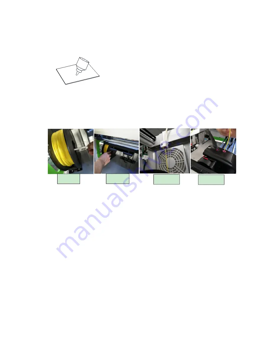
2) Consumables installation

Remove the accessory "consumables" from the packaging carton and install the filament tray

correctly on the carriage

as shown in Figure 1&2

, and the consumable material is drawn out from the

inside of the tray (strictly install in the direction shown. Don’t install upside down).

Trim the head of filament, then get it through the thread guide

tube to the nozzle case

(not really

get through the

case

). Then open the machine, select the preheat nozzle button, set the nozzle

temperature (PLA material around 200

, ABS material around 220

), until the nozzle heated to

the set temperature, and then press the nozzle assembly on the left clamping gear handle. Insert the
material into the throat forcedly, and observe the nozzle, a smooth material out shows that it is
installed successfully.

3) Adjust Printer Optical Flatness

The correct position of printing platform should be in the vertical plane with nozzle. This can

greatly reduce the print failure rate, ensure a more stable printing process, and get the better effect of
the print model. The printing platform is mechanically biased due to transportation or re-installation,
etc. If the following two conditions occur during the printing of the bottom border, the platform needs
to be leveled again.

Consumables not sticking on the platform means the platform is too low. Then it needs for

appropriate increase.

Consumables extruding not smoothly means the platform is too high. Then it needs for a

corresponding reduction.

Figure 1

Figure 3

Figure 2

Figure 4

Summary of Contents for INVENTOR PRO

Page 1: ...FDM 3D Printer INVENTOR PRO Yiwu Instone 3D Technology Co Ltd USER S MANUAL ...

Page 2: ... of User Interface 8 Machine Installation and Operation Guide 11 Software Installation and Operation Guide 13 1 Install the Instone 3D 13 2 Basic settings 14 3 Advanced parameters instruction 15 4 Expert Settings 16 5 Load model file 17 6 Rotate 17 7 Scale 18 8 Mirror 18 9 Right mouse menu 18 Online printing and firmware updates 19 Precautions and FAQ 20 WIFI Module Operating Guide 22 ...

Page 3: ...d without prior written authorization This manual is copyrighted and we reserves all the rights of the final explanation Important Security Information Failure to follow the instructions in this manual may result in fire equipment damage property loss or personal injury Before using the product please refer to the Quick Start Guide and User s Manual Operation 1 For INVENTOR PRO and power adapter p...

Page 4: ...amage or personal injury Squeeze Involve cutting The INVENTOR PRO has mounts of motion components Avoid contact with these moving parts during operation To prevent the body is squeezed involved cutting and other injuries Caution hot scald 1 During working the nozzle floor and other components of machine will produce high temperature Please avoid direct skin contact with these parts 2 Do not touch ...

Page 5: ...ng the nozzle will squeeze out the material Make sure that the distance between the nozzle and the print platform is at least 50 mm or the nozzle might be blocked Overview INVENTOR PRO series with the ownership of several patents is the new generation of 3D printer with independent design development and manufacturer After simple training you are able to create whatever model you like even you hav...

Page 6: ... 6 Get to know your INVENTOR PRO ...

Page 7: ...ayer thickness 0 1 0 3mm Nozzle diameter 0 4mm Nozzle number Single Changing material midway Support WIFI Support User interface 3 5 inch touchscreen Software requirement Enclosed software Inston3D Cura Extended software Slic3r Repetier host Simplify3D File formats STL OBJ G Code OS Windows Linux Mac Consumables specifications Printing material ABS PLA Diameter 1 75mm Color Colorful Machine specif...

Page 8: ... 8 Brief Introduction of User Interface Logical Relationship HOMEPAGE SYSTEM ...

Page 9: ... 9 TOOL FILE CHOOSE FILE OPERATION PRINTING INTERFACE PRINTING TOOL NUM KEYBOARD MANUAL PREHEAT ...

Page 10: ... 10 FILAMENT LEVEL FAN WORKING CONDITION INFO WIFI ...

Page 11: ...tall upside down Trim the head of filament then get it through the thread guide tube to the nozzle case not really get through the case Then open the machine select the preheat nozzle button set the nozzle temperature PLA material around 200 ABS material around 220 until the nozzle heated to the set temperature and then press the nozzle assembly on the left clamping gear handle Insert the material...

Page 12: ...eat the operation until the main interface says LEVELING SUCCESSFULLY 4 Model Printing Copy the already converted GCODE model file to the SD card the standard SD card already contains 3 test models The SD card as shown in the left Figure Insert the SD card to the slot with gold finger side up then select the Print menu in the file directory list select the file you want to print and wait for print...

Page 13: ...l ver 15 04 6 1 Open the folder in the U disk with the machine then double click Instone3D_15 04 6 Choose the installation directory in the first interface or default then click NEXT 2 All the requests during installation just click YES Then click NEXT to finish the installation ...

Page 14: ... 14 2 Basic settings ...

Page 15: ... 15 3 Advanced parameters instruction ...

Page 16: ... 16 4 Expert Settings ...

Page 17: ... 17 5 Load model file 6 Rotate ...

Page 18: ... 18 7 Scale 8 Mirror 9 Right mouse menu ...

Page 19: ...location of pc ports Baudrate 115200 then click OK 4 When Print with USB shows above the icon which in the right figure it means successful connection 5 Following the Operation Guide in last chapter load the model in this program adjust the slice parameters when slicing finished click Print with USB printer will start heating printing etc automatically Firmware updates The factory has installed th...

Page 20: ...d Question 2 No filament comes out from the nozzle A If this problem happens with clatters from nozzle when install the new filament please check whether the filament head inserted to the tube inside the nozzle whether it stuck in the mouth of nozzle then take out the filament re insert after trim B If it is determined that the head has entered the heating head but with clatters check if the curre...

Page 21: ...e paint the printing glue The platform is not leveled correctly Too large gap between nozzle and platform Re level the platform With large gap the filament can t stick on the board totally with small gap the risk of nozzle stuck will be increased or even broken the glass board Remove the radiator and fan Figure 2 Clean the stuck material Figure3 Unblock test if ok install the right cover Figure4 ...

Page 22: ... 22 WIFI Module Operating Guide ...

Page 23: ... 23 Thanks for choosing Instone The End ...

Reviews: