background image


Page 29 of 38


SPAN 500 BRIDGED TOWER  


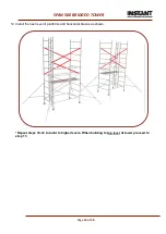
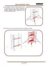
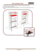
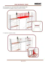
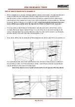
31. Install the next level ladder frames and walk through frames. Install the temporary gate at ground 

level. Ensure the temporary gate remains locked.


12. Install the four diagonal braces on each tower from the as shown. 


Summary of Contents for BS 1139-6

Page 1: ...Spandeck 500 Bridged Tower ASSEMBLY MANUAL DESIGNATION BS 1139 6 2014 EN1004 CEN 1298 IM en SPAN 500 BRIDGED TOWER Date 08 11 18 Rev 5...

Page 2: ...BALLAST 7 USE OF PREFABRICARTICATED SCAFFOLDS FOR ACCESS TO ADJACENT STRUCTURES 7 CARE AND MAINTENANCE 7 TOWER CONFIGURATION 6m TOWER 8 PART LIST 9 Tower Parts List 9 Spandeck Parts List 10 TOWER SEL...

Page 3: ...two platforms evenly distributed SPANDECK SAFE WORKING LOAD C x D 275 Kg over two spandeck evenly distributed TOTAL SAFE WORKING LOAD ON TOWER CONFIGURATION A x D 825 Kg Max evenly distributed SAFE W...

Page 4: ...castor into adjustable leg Step2 Ensureinterlock clipsarereleasedfrom thebase frames bottomframes Step 3 Install castor leg assembly to frame by pushing the leg into the frame tube This should be done...

Page 5: ...Ensure that couplers are suitable for 50mm diameter aluminium tube Do not use boxes or steps to gain additional height If extra height required contact your distributor to get extra components Do not...

Page 6: ...irt or paint from adjustable legs with a light brush lightly oil the leg locks Do not strike or hammer components Do not throw or drop onto hard surfaces Lightly oil spring mechanism of the hooks For...

Page 7: ...and the place being accessed through which a person tools or materials could fall The platform of the scaffold tower and the surface onto which a person will step when accessing another place must be...

Page 8: ...Page 8 of 38 SPAN 500 BRIDGED TOWER TOWER CONFIGURATION 6m TOWER...

Page 9: ...Horizontal Brace 2 1 18 26 26 26 34 8 40365 01 Diagonal brace 2 2 12 18 24 30 36 9 46094 03 2 Trapdoor Platform 17 12 2 4 4 4 6 10 46361 Platform 17 2 2 2 2 2 11 Walk through Frame 12 5 2 2 2 2 2 12 5...

Page 10: ...4 4 88116 5 0m Guardrail Tube 5 5 4 4 4 4 4 88118 5 5m Guardrail Tube 6 1 4 4 4 4 4 88120 6 1m Guardrail Tube 6 8 4 4 4 4 4 88122 6 7m Guardrail Tube 7 7 4 4 4 4 4 88124 7 3m Guardrail Tube 8 5 4 4 4...

Page 11: ...ace onto the vertical tube of the frame just above the collar with the claw facing outwards This will support the frame Note Release brace latch for ease of fitting 3 Fit horizontal brace onto the opp...

Page 12: ...BRIDGED TOWER 4 Fit 4 rung ladder and non ladder frames to the 2 rung frames matching the ladder frames as shown Insert interlock clips into frame holes to lock frames together 5 Fit diagonal braces...

Page 13: ...o the trapdoor opens to the outside of the structure Note Apply wind lock when platform is installed as shown 7 Using the 3T method install the horizontal braces on the 5th and 6th rung on both sides...

Page 14: ...ion the lower clamp so that the lower arm is as close to horizontal as possible Adjust the length of the leg when using telescopic stabilisers Ensure stabiliser foot has a firm contact with the ground...

Page 15: ...of 38 SPAN 500 BRIDGED TOWER 10 Install the next level ladder frames and non ladder frames 11 Install the four diagonal braces from the 5th to the 7th and from the 7th to the 9h rungs on both sides a...

Page 16: ...e 16 of 38 SPAN 500 BRIDGED TOWER 12 Install the next level of platforms and horizontal braces as shown Repeat steps 10 12 to build to higher levels When building to top level of tower proceed to step...

Page 17: ...0 BRIDGED TOWER 13 Install the next level ladder frame and walk through frame Install the temporary gate at ground level Ensure the temporary gate remains locked 14 Install the four diagonal braces on...

Page 18: ...R 15 Install the trapdoor and non trapdoor platforms on the 12h rung of the tower structures Note the orientation of the trapdoors 16 Using the 3T method install the horizontal braces on the 13th and...

Page 19: ...and brace at each end Detach couplers from horizontal braces couplers fixed to handrail now have centres as spandeck 18 Temporally couple both towers together by fixing couplers mounted on handrail to...

Page 20: ...top coupler Slide the pin up the tube to allow for installation 20 Mount the required number of Spandeck guardrail posts to the side of the spandeck Do the same for the opposite side of Spandeck 21 S...

Page 21: ...ion can be safely undertaken 24 Manually hoist one of the spandeck sections to the working level one or more persons may be required on each tower or as specified in the mechanical lift and handling m...

Page 22: ...he other end With a person at each end of the handrail tube from the protection of the tower securely fasten the tube to the spandeck post couplers With both ends of the tube secured secure the handra...

Page 23: ...Page 23 of 38 SPAN 500 BRIDGED TOWER 29 Install toe boards as shown 30 Install knee braces as shown...

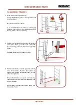
Page 24: ...ontal brace onto the vertical tube of the frame just above the collar with the claw facing outwards This will support the fame Release brace latch for ease of fitting 3 Fit horizontal brace onto the o...

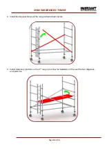
Page 25: ...f 38 SPAN 500 BRIDGED TOWER 4 Install the diagonal braces at the rung positions shown below 5 Install temporary platform on the 2nd rung up to allow for installation of the next frames diagonals and p...

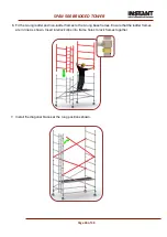
Page 26: ...t the 4 rung ladder and non ladder frames to the 4 rung base frames Ensure that the ladder frames are in line as shown Insert interlock clips into frame holes to lock frames together 7 Install the dia...

Page 27: ...rapdoor opens to the outside of the structure Note Apply wind lock when platform is installed as shown 9 Using the 3T method install the horizontal braces on the 7th and 8th rung on both sides of the...

Page 28: ...ion the lower clamp so that the lower arm is as close to horizontal as possible Adjust the length of the leg when using telescopic stabilisers Ensure stabiliser foot has a firm contact with the ground...

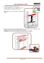
Page 29: ...DGED TOWER 31 Install the next level ladder frames and walk through frames Install the temporary gate at ground level Ensure the temporary gate remains locked 12 Install the four diagonal braces on ea...

Page 30: ...R 13 Install the trapdoor and non trapdoor platforms on the 10th rung of the tower structures Note the orientation of the trapdoors 14 Using the 3T method install the horizontal braces on the 11th and...

Page 31: ...Page 31 of 38 SPAN 500 BRIDGED TOWER 15 Follow steps 17 27 from the 6m build to install spandeck safely 16 Reposition the outriggers 90 degree to platform as shown 17 Install the T coupler as shown...

Page 32: ...Page 32 of 38 SPAN 500 BRIDGED TOWER 18 Install toe boards as shown 19 Install knee braces as shown...

Page 33: ...struction If the spandeck cannot be hoisted up between the towers there are some alternative options o Install spandeck as instructed in 6m build sequence and move tower into place o Rope the spandeck...

Page 34: ...ll the walk through frames ensuring that the frame openings are positioned on the same side as shown below Install the trapdoor and non trapdoor platforms on the 4th rung above the platform below Note...

Page 35: ...Page 35 of 38 SPAN 500 BRIDGED TOWER Install the spandeck following the steps from the 6m build sequence steps 17 27 Use right angle couplers to couple on the handrails to the tower as shown below...

Page 36: ...The knee brace is fixed between the Spandeck side extrusion and a vertical frame and is normally fitted at an angle of about 45 deg The end of the knee brace which clamps to the clamp to the Spandeck...

Page 37: ...t the base do not use machinery to push or pull the tower Once moved prepare the tower for use Use the pre use inspection checklist at the end of this manual Check all castors and stabilisers are in f...

Page 38: ...Page 38 of 38 SPAN 500 BRIDGED TOWER...

Reviews: