


PAGE 9
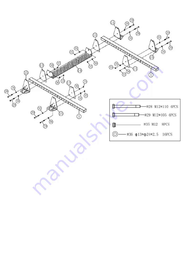
STEP 1.
BOTTOM SUPPORT FRAME ASSEMBLY
Refer to the illustration above for location and orientation of components.
This step consists of a left side and a right side.
•
Fasten with Bolt (28), Washer (36), and Locknut (35). Connect Bottom Foot Plate (15) to
Bottom Base Frame (1), Bottom Inner Plate (13), and the Bottom Cross Brace (14), place
these items towards the one end of the Bottom Base Frame.
•
Repeat Step for the Opposite side.
•
Fasten with Bolt (29), Washer (36), and Locknut (35). Connect Bottom Foot Plate (15) to
Bottom Base Frame (1), and Bottom Inner Plate (13), and the Bottom Cross Brace (14),
place these items towards the one end front of the Bottom Base Frame.
•
Repeat Step for the Opposite side.
•
Together, these Items form the Bottom support Assembly.
Summary of Contents for FPC1
Page 1: ...PAGE 1 FPC1 FULL POWER CAGE ...
Page 4: ...PAGE 4 ...
Page 5: ...PAGE 5 EXPLODED VIEW ...
Page 7: ...PAGE 7 COMPONENTS LIST 13 X 4 4 X 1 2 X 2 40 X 2 12 X 2 15 X 4 5 X 4 3 X 1 1 X 2 ...
Page 8: ...PAGE 8 HARDWARE PACK ...
Page 17: ...PAGE 17 ...
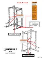
Page 18: ...PAGE 18 Labels Placement FPC1 FULL POWER CAGE ...
Page 19: ...PAGE 19 ...