background image

5

Product Overview

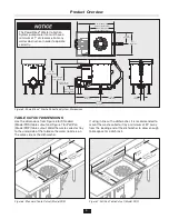
44.95"

(1142 mm)

21.5"

(546 mm)

24.95"

(634 mm)

3"

(76 mm)

20"

(508 mm)

10.75"

(273 mm)

23.75" (603 mm)

Standard (Model PRS)

35.5" (902 mm)

Pot/Pan (Model PRP)

33"-36"

(838-914 mm)

28.93"-31.93"
(735-811 mm)

25.41"-28.41"

(645-722 mm)

7.93"-10.93"

(201-278 mm)

Figure 5. PowerRinse

®

 Waste Collection System Dimensions

TABLE CUTOUT DIMENSIONS 

Use the dimensions from Figure 6 for Standard  
(Model PRS) table cutout and Figure 7 for Pot/Pan 
(Model PRP) table cutout. Weld the waste collector tray 
to the underside of the table so the water nozzle is on 
the same side as the dishwasher. 

 
If using in line with a dishwasher, it is recommended to 
mount the waste collector tray a minimum of 24" away 
from the loading end of the dishwasher to allow enough 
table space for a dish rack.

24" m

in.

(60

9.6 m

m)

Dis

h R

ack S

pa

ce

   D

ish

wa

she

r

Wa

ter

No

zzl

e

24-

3/4

"

(62

8.7 m

m)

22-1

/4"

(565

.2 m

m)

Dis

h F

low

Figure 6. Standard Table Cutout (Model PRS)

36

-1/

2"

(92

7.8 m

m)

22-1

/4"

(565

.2 m

m)

   D

ish

wa

she

r

24" m

in.

(60

9.6 m

m)

Dis

h R

ack S

pa

ce

Dis

h F

low

Wa

ter

No

zzl

e

Figure 7. Pot/Pan Table Cutout (Model PRP)

The PowerRinse

®

 Waste Collection 

System pump motor fan must have a 

minimum of 1" of clearance from any 

wall or obstruction in order to operate 

correctly.

Summary of Contents for PowerRinse PRP Series

Page 1: ...ctions contained in this manual NOTICE is used to address practices not related to physical injury CAUTION indicates a hazardous situation which if not avoided could result in minor or moderate injury...

Page 2: ...lectrical Electrical Disconnect Switch 8 Electrical Connections 9 Initial Setup and Verification Prepare the System 9 Operating Instructions Main Operation 10 Timed Run Feature 12 To Empty Scrap Baske...

Page 3: ...e for oversized cookware such as large sheet pans The PowerRinse Waste Collection System is CUL US Listed when installed in conjunction with InSinkErator pumps and controls and per the installation in...

Page 4: ...Waste Collection System o Screwdriver o Pipe wrench o 7 16 wrench or socket o Tools and materials necessary to install the power line drain line and the hot and cold water The following items are nee...

Page 5: ...nozzle is on the same side as the dishwasher If using in line with a dishwasher it is recommended to mount the waste collector tray a minimum of 24 away from the loading end of the dishwasher to allo...

Page 6: ...t to right dish flow CHANGING THE CONTROL LOCATION Optional to relocate the control remove and save four 4 bolts and nuts Reposition box on other side of tank and secure with previously removed hardwa...

Page 7: ...r valve If lines are reversed mixer valve will not operate properly after adjustment It is recommended that ball type shutoff valves be installed in line with the cold and hot water lines A minimum of...

Page 8: ...the line disconnect switch before system will start Ensure all connections are tight and leak free including rubber boots and plumbing connections supplied by the manufacturer before moving forward a...

Page 9: ...and connect as shown NOTE Be sure to use liquid tight conduit and conduit fittings Close front panel and tighten screws on top cover retainers to secure INITIAL SETUP AND VERIFICATION PREPARE THE SYST...

Page 10: ...iewed from the motor end If rotation is counter clockwise turn off power supply open front panel and switch L1 and L2 connections Turn off unit by pressing the STOP button Indicator light turns off NO...

Page 11: ...nce tank has reached optimal fill level approximately 70 seconds after pushing the START button Adjust ball valve until water plume hits desired location inside tray area recommended location is the c...

Page 12: ...e the Timer ON and OFF switch Move switch to desired position To adjust timer Open the control panel Locate the Timer Switch Rotate time range switch or main dial to desired settings as shown The time...

Page 13: ...be cleaned daily at end of shift and as needed throughout the day Turn off unit and empty scrap basket see above instructions Pull overflow tube to drain water inside waste collector tank Rinse cover...

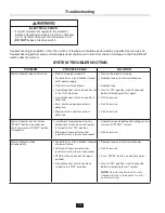
Page 14: ...Replace fuse or reset circuit breaker Replace fuse Turn to ON position wait 30 seconds before attempting to start again Call for service Call for service Call for service Waste Collector will start wh...

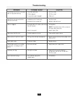
Page 15: ...er NOTE Scrap basket should be in place at all times during operation Adjust mixer valve Water does not fill in tank Overflow pipe not in drain Place overflow pipe in drain Water system is too hot or...

Page 16: ...845 8345 for the nearest InSinkErator Authorized Service Agency or to reach Technical Support ELECTRICAL SHOCK Turn off all electrical supply to the collector before attempting any work on it Use a v...

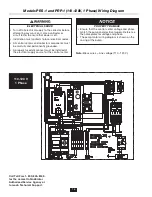
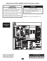
Page 17: ...permanently grounded A properly fused disconnect must be installed at the electrical supply source for the control center 120 V 1 phase 1 2 to 2 HP 208 220 240V 1 Phase PROPERTY DAMAGE Ensure that the...

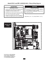
Page 18: ...nkErator Authorized Service Agency or to reach Technical Support Note Black wires Line voltage 208 220 240 V ELECTRICAL SHOCK Turn off all electrical supply to the collector before attempting any work...

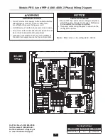
Page 19: ...Erator Authorized Service Agency or to reach Technical Support Note Black wires Line voltage 460 480 V ELECTRICAL SHOCK Turn off all electrical supply to the collector before attempting any work on it...

Page 20: ...rmed on your InSinkErator Product by anyone other than an authorized InSinkErator service representative If a covered claim is made during the Warranty Period Manufacturer will through its authorized...

Reviews:

Related manuals for PowerRinse PRP Series