background image

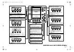
To adjust Sensitivity, press MENU
repeatedly until the Sensitivity
heading is displayed. When the
Sensitivity menu appears, use
the UP ARROW to increase the
sensitivity, or the DOWN
ARROW to reduce sensitivity. To
sequence through the available
settings, press and hold either
ARROW button. Release the
button at the setting you want
to select. 

After an adjustment is made, the menu disappears and the new sensitivity
setting is in affect. If additional time is needed to study a menu, press and hold
the MENU button and the menu will remain on-screen indefinitely. If you need
to make an additional adjustment, press the UP ARROW or DOWN ARROW
button.

Depth Range.

The Depth Range function

controls the vertical distance displayed on
the graphic area of the display. There are
nine depth ranges available. The top of the
range is always 0, or the surface of the
water. Ranges of 0–15', 0–30', 0–60',
0–120', 0–180', 0–240', 0–360', 0–480',
and 0–600' are available. In the metric
selection , ranges of 0–5, 0–10, 0–20, 0–40,
0–60, 0–80, 0–110, 0–150, and 0–185
metres are available. The range that
positions the bottom depiction closest to the
bottom of the screen, will best utilize the
available display resolution.

The 450TX automatically adjusts the depth range depending on the depth of
the water. The unit tries to maintain the bottom depiction about 

²⁄₃

down the

total range (for example, in 6m (20') of water, the 0-10m (0-30') range would
be selected). This provides the best display resolution and therefore the best
target separation possible.

16

USING THE 450TX

MENU FUNCTIONS

High Sensitivity    Sensitivity at “0”

Low Sensitivity

530977-1r11015E  11/6/01  12:09 PM  Page 16

Summary of Contents for Tri Beam 450TX

Page 1: ...Operations Manual 530977 1r11015E 11 6 01 12 09 PM Page 1 ...

Page 2: ...operations manual carefully in order to get full benefit from all the features and uses of your Humminbird product Also to register your purchase and help us learn more about you please fill out the warranty registration card at the back of this manual WARNING This device should not be used as a navigational aid to prevent collision grounding boat damage or personal injury When the boat is moving ...

Page 3: ...on 2 USING THE 450TX 6 How Sonar Works 6 Simulator Operation 7 What You See On Screen 8 Control Functions 12 Menu Functions 15 Section 3 ADVANCED FEATURES 26 Using Diagnostic 26 Using Alternative Transducers 29 Section 5 MAINTENANCE 31 Maintenance and Troubleshooting 31 Specifications 35 TABLE OF CONTENTS PN530977 1 Rev 11015E 530977 1r11015E 11 6 01 12 09 PM Page 1 ...

Page 4: ...of the many accessories available and ordering information All Humminbird accessories are available through your full service Humminbird dealer INSTALLATION OVERVIEW The 450TX consists of two primary components to install the control head and the transducer The control head contains the sonar transmit and receive circuitry as well as the user controls and display It should be installed in a locati...

Page 5: ...he outside of the boat hull This technique produces the least signal loss and provides a way to adjust the transducer after installation The mounting hardware included is designed to protect both the boat and the transducer should the boat strike debris in the water or when trailering As an alternative to transom mounting it is possible on many fiberglass hulled boats to glue the transducer on the...

Page 6: ... transducer can be adapted for portable installations using part number MHX PT2 This accessory adapts your trans ducer to a suction cup mount for temporary installation on the boat hull or other surface Trolling Motor Mounting The standard transducer can also be adapted to mount on most trolling motors using part number AD STM 7 This accessory includes a bracket and hose clamp that allows mounting...

Page 7: ...TION Now that you have determined the transducer mounting method you can begin installation of the 450TX The fold out installation guide included provides detailed step by step instructions for installation of the control head and transducer For transom mount transducer installations you will need the mounting template at the front of this manual In addition to the parts included you need the foll...

Page 8: ...nar signal The 450TX is a dual frequency tri beam unit and generates three distinct sonar signals one narrow two wide Each signal is optimized for a particular purpose First the center beam transmits at a frequency of 200 kHz in a 20 degree narrow symmetrical pattern for greater depth capability and excellent detail Information from this center beam is used to draw the graphic representation of th...

Page 9: ...s screen is shown simply press the DOWN ARROW until Simulator is highlighted When the screen times out the unit will be in simulator mode Once the Simulator mode is selected the next screen will allow you to select either down simulator or side simulator The down selection simulates normal operation of the unit with the Tri beam transducer connected Down simulator is the default setting so if no a...

Page 10: ...n order to retain user settings selected when in simulator mode If no transducer is detected the unit defaults to pre selected options when powered off What You See On Screen Your 450TX uses a 160 x 160 matrix FSTN LCD display This display provides outstanding viewability in all light conditions over a wide range of temperatures At initial power up the 450TX uses settings that were set at the fact...

Page 11: ...creen is the zero line representing the surface of the water Occasionally there is a gap in this line This gap indicates the unit is updating the display even if the bottom is not visible on screen or if the bottom information is not changing New sonar information appears on the right side of the graphic area of the display and moves to the left as new information is displayed The 450TX automatica...

Page 12: ...ular variations that match wave timing Structure Structure is defined as any object physically attached to the bottom The sonar configuration of the 450TX is optimized to give the most accurate depiction of bottom structure possible Grass trees stumps wrecks or other debris are accurately displayed however the depiction of these objects varies with boat speed and direction The best way to learn to...

Page 13: ...guish fish size between varying species The signal intensity is normalized for depth so that a small fish close to the boat does not appear as a large fish symbol ID adds an additional piece of information to help the user locate fish On selected fish symbols the digital depth of the designated fish is drawn to help locate the fish vertically This is especially helpful in setting bait depths or fo...

Page 14: ...n the backlight is on the 450TX will consume more power than with the backlight off This is important when using the 450TX in a portable configuration powered by a separate battery or when powering the unit from a trolling motor battery When powering the unit from a battery such as in portable applications you can prolong the battery life by using the backlight at a minimum The three lower buttons...

Page 15: ... depiction If a Wide Side transducer is being used see Using Alternative Transducers the VIEW button is used to select one of four views available Both Left Right and Down You can select side simulator to view this presentation even if a Wide Side transducer is not connected Menu MENU displays a menu on screen for adjustment In normal operation pressing MENU repeatedly cycles through all available...

Page 16: ...screen In these situations pressing the ARROW button affects the function of the active last used menu This is a short cut to menu operation An abbreviated menu appears on screen while the adjustment is made and times out A frequently used menu can be adjusted very quickly using this technique After an adjustment is made to a menu function the menu times out after a few seconds and the unit return...

Page 17: ...er has the option of adjusting the Sensitivity higher or lower based on personal preference You can select one of 11 sensitivity settings from 5 to 5 A setting of 0 factory setting has no effect on the automatic sensitivity control Increasing the sensitivity 1 through 5 enables the unit to display the information from progressively smaller sonar returns By decreasing the sensitivity 1 through 5 th...

Page 18: ... displayed on the graphic area of the display There are nine depth ranges available The top of the range is always 0 or the surface of the water Ranges of 0 15 0 30 0 60 0 120 0 180 0 240 0 360 0 480 and 0 600 are available In the metric selection ranges of 0 5 0 10 0 20 0 40 0 60 0 80 0 110 0 150 and 0 185 metres are available The range that positions the bottom depiction closest to the bottom of...

Page 19: ...elect AUTO Zoom The 450TX uses a greatly enhanced Zoom capability called TruZoom which offers expanded information on a select area of sonar information Zoom is similar to Depth Range because it controls the range of information displayed on screen Zoom however allows selection of ranges beneath the surface so any area of water between the surface and the bottom can be enlarged to provide more det...

Page 20: ...he Automatic Zoom keeps the bottom in view even in quickly changing terrain Manual Zoom provides detailed information of any area from the surface to the bottom In Manual Zoom the Zoom range does not move as the terrain changes To operate Zoom press MENU repeatedly until the Zoom menu is on screen Three options are available Off Factory Setting Auto Automatic bottom tracking Zoom and Manual User c...

Page 21: ... the Zoom menu returns to Zoom Off Depth Alarm The 450TX contains an audible alarm to warn you of shallow water depths The alarm is adjustable to depths of 6m 2 to 30m 99 When the alarm is enabled an audible alarm sounds if the water beneath the boat is equal to or less than the selected alarm depth The alarm sounds continuously for about five seconds and then intermittently to remind you that you...

Page 22: ...TX emits an audible beep when the selected size fish symbol appears on screen Fish Alarm settings are remembered when the unit is powered off Triplog Triplog provides a running log of information based on input from the Temp Speed sensor Since Triplog requires information from the Temp Speed sensor to operate if this sensor is not detected by the 450TX the Triplog menu will not appear as an option...

Page 23: ...l operation of the product There are thirteen Option menus Contrast Display Speed Battery Alarm Bottom Black Fish ID Numeral size Transducer Units Speed Units Depth Languages Speed Offset Depth Offset and Reset Press the View button at any time to exit options and return to normal operation Contrast The Contrast function allows the user to control the level of contrast of the LCD display The 450TX...

Page 24: ...the voltage level at which the Battery Alarm activates At the Battery Alarm menu under options you will note that the default setting is OFF Push the DOWN ARROW BUTTON to select the feature ON Push the DOWN ARROW BUTTON again to move into the ADJUST BATTERY ALARM setting Using the UP and DOWN ARROW BUTTONS select a voltage between 9 0 and 12 0 When the voltage drops below your selected voltage an ...

Page 25: ...different size fish symbols Further identification shows which beam the fish is detected in The 450TX also displays the depth beneath the surface with the corresponding fish symbol Selecting Adjust and making incremental changes enhances the fishfinder s ability to identify sonar returns as fish symbols Increasing the value to a number greater than zero shows more fish symbols on screen In this ca...

Page 26: ...ide side transducer no adjustment to this menu is needed unless the transducer develops a fault which is a rare occurrence The factory setting for the Transducer menu is Auto The transducer menu selections will be remembered when the 450TX is turned off If a faulty transducer is connected the 450TX may not change the screen presentation to match the transducer In this instance you may need to manu...

Page 27: ...OWN ARROW BUTTONS to scroll through the list The 450TX remembers this selection even when the unit is powered off Speed Offset The Speed Offset option allows the user to compensate for differences in hull design and its effect on the accuracy of the speed measurement If there is a discrepancy between the indicated speed and another speed measurement device on the boat the speed measurement can be ...

Page 28: ...setting is not the cause for the perceived problem USING THE DIAGNOSTIC FEATURE The 450TX contains a powerful diagnostic tool that can aid in determining the cause of a problem To use the Diagnostic feature select the Diagnostic feature on the start up menu on the initial screen Self Test Initially the 450TX will perform a self test This test confirms the operation of all internal circuitry At the...

Page 29: ...voltage problems The current input voltage is displayed If voltage fluctuations or power supply in excess of 20 VDC or less than 10 VDC is suspected use the diagnostic screen to confirm input voltage Often small outboard motors do not effectively regulate voltage when operated at high engine speeds Use Diagnostic while running the boat at high speeds to show the voltage gain Also if you are using ...

Page 30: ...t as measured by each of the three beams With the boat stationary over a flat consistent bottom the sonar returns from the left and right beams should be identical Any discrepancy between these signals may indicate a problem with the location of the transducer Often voids or irregularities in the laminated hull of a fiberglass boat will block or degrade one or more of the sonar signals By referrin...

Page 31: ...The downward beam is 200 kHz with a 24 degree area of coverage This beam maintains a continuous digital depth readout from the bottom directly beneath your boat The side beams are 455 kHz with a 16 degree area of coverage The side looking elements can be used independently or together to locate targets near the surface of the water on either side of your boat The Wide Side transducer can be connec...

Page 32: ...iewing both left and right sides simultaneously gives you an excellent tool when searching for bait fish in open water or when following a creek bed However you will have a greater display resolution if you view only one side The down view is similar to the traditional view when using the standard transducer however there is no Tri Beam information available such as fish location When operating in...

Page 33: ...ucer with liquid detergent Pivoting the transducer up in the bracket may allow better access for inspection or cleaning If your boat remains out of the water for a long period of time it may take some time to wet the transducer when returned to the water Small air bubbles can cling to the surface of the transducer and interfere with proper operation These bubbles dissipate with time or you can wip...

Page 34: ... be good Check the power connection to the 450TX It is possible to force the power cable connector into the cable holder incorrectly If the connector is reversed the unit will not work Examine the contacts on the back of the unit to ensure there is no corrosion Finally ensure the unit is firmly seated on the mount The electrical contacts are not made until the unit is fully seated Ensure the metal...

Page 35: ... the trolling motor is out of water no sonar information appears If none of the above solve the problem inspect the transducer cable from end to end for breaks kinks or cuts in the outer casing of the cable If the transducer is connected to the unit through a switch temporarily connect it directly to the unit and try again If none of these items identifies an obvious problem the transducer itself ...

Page 36: ...the Diagnostic screen Use this readout to determine if the voltage exceeds 20 VDC 8 The screen begins to fade out Images are not as sharp as normal Check the input voltage using Diagnostic The 450TX will not operate on input voltages below 10 VDC 9 The display shows many black dots at high speeds and high sensitivity settings You are seeing noise or interference caused by one of several sources No...

Page 37: ...Display FSTN LCD LCD Matrix 160 H x 160 V Viewing Area 10cm H x 7 6cm V V 4 H x 3 Mounting Quick Disconnect Mount Unit Size 19 4cm H x 20cm W x 11cm D 7 H x 7 W x 4 D Transducer Standard XT 6 TB 90 Transducer Cable Length 6 metres 20 Depth Ranges 5 10 20 40 60 80 110 150 185 metres 15 30 60 120 180 240 360 480 600 Zoom Ranges 2 5 10 15 20 28 38 46 metres 7 15 30 45 60 90 120 150 530977 1r11015E 11...

Page 38: ...er ALIGN ONE CORNER WITH LOWER EDGE OF TRANSOM TOP Use 4 0mm drill bit and drill the two holes that most closey match your hull composition Drill Drill For Fiberglass hulls For Aluminum hulls 530977 1r11015E 11 6 01 12 09 PM Page 36 ...

Page 39: ...P N 530977 1 530977 1r11015E 11 6 01 12 09 PM Page 37 ...

Page 40: ...530977 1r11015E 11 6 01 12 09 PM Page 38 ...

Reviews: