background image

getting

started

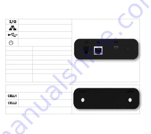
4 Pin IO Connector (Power/IO)
RJ45 Ethernet Port

USB Micro-B Port

Power Button

Green Solid

Normal Operation

Green Blinking Charging Battery (Off)
Blue Solid

Good Battery

Yellow Solid

Mid-Level Battery

Red Solid

Low Battery

Red Blinking

System Error

White Blinking Startup/Software 

Update In Process


Primary Cellular Antenna

Auxiliary Cellular Antenna

Summary of Contents for Skyus 100 Series

Page 1: ...Quick Start Guide SKYUS 100 SERIES...

Page 2: ...wer Button Green Solid Normal Operation Green Blinking Charging Battery Off Blue Solid Good Battery Yellow Solid Mid Level Battery Red Solid Low Battery Red Blinking System Error White Blinking Startu...

Page 3: ...Blinking Wi Fi On Bluetooth On Blue Fast Blink Bluetooth Pairing Mode Mobile Network Green Solid Connected Good Signal No Traffic Green Blinking Connected Good Signal Traffic Yellow Solid Connected M...

Page 4: ...reless service provider to activate the SIM card and data plan 3 Connect the device to a power supply and ensure that the device is turned on NOTE If using the power cable make sure it is connected to...

Page 5: ...iate power source 2 Ensure that the device is powered on 3 Connect the device using the SSID and Wi Fi password printed on the label on the bottom of the device The default SSID is in the format SKYUS...

Page 6: ...y skyus or 192 168 1 1 on any connected device to access the device Web Interface Home page 2 Click Sign In 3 Use the login credentials from the labels on the bottom side of your device to log in 4 Vi...

Page 7: ...ource Required Power over USB Min 5V 1A Required AC Power 6 32 VDC Required Battery Power 4400 mAh Up to 12 Hrs Run Time Embedded connection management cloud connectivity and edge processing Networkin...

Page 8: ...Series Device 4400 mAh Rechargeable Battery Whip Antennas AC or DC Power Cable OPTIONAL ACCESSORIES Whip Mag Mount Bulkhead Mount and Adhesive Mount Antenna Options Available USB Cable USB AC Adapter...

Page 9: ...selected mounting surface and anchors if needed 2 Ensure the head of the screw for 1 is kept approx 1 8 From mounting surface 3 Install the device onto the screw with hole 1 4 Install screws through h...

Page 10: ...documentmaybereproduced storedinorintroducedintoaretrievalsystem or transmittedinanyformorbyanymeans electronic mechanical photocopying recordingorotherwise orforanypurpose withouttheexpresswrittenper...

Reviews: