


— 7 —
Section III
OPERATING THE 634 RECEIVER
Hey, why is the screen flashing?
The 634 has two alarms that indicate reception problems.
These are detailed later in this section, but you may encoun-
ter one or both as soon as you power up the receiver. These
alarms identify a problem and flash lighted blocks on and
off, making the alarm quite visible even across the room.
If the 634 has not yet
been set up for use, the
LOW SIGNAL
and/or
AU-
DIO LOSS
alarms will
begin to flash soon after
the receiver is powered
up. If you push or turn the knob, you will get a few seconds
respite from the flashing, enough time to navigate to any of
the setup menus. Of course, once a station has been tuned-
in properly the alarm condition will be reset.
Whenever you are in the ‘edit mode’; that is, you have en-
tered a menu to edit (make a change to) a setup item, the
front-panel flashing alarm is inhibited while that parameter
is being programmed. The edit mode times out after 30 se-
conds if no entry is made, and a flashing alarm will cancel
the edit mode as well.
The rear-panel tally outputs will always be active for the du-
ration of an alarm, even when front-panel flashing is tempo-
rarily inhibited.
NOTE:
Flashing alarms are not to be confused with ‘blink-
ing’ menu callouts that indicate options for editing.
Menu Navigation Basics
By the time you’ve read this, you’ve probably already fig-
ured out the 634 receiver menu for yourself; it’s really quite
intuitive. Quite simply: 1)
turn
the knob to navigate from
one menu to the next, 2)
push
the knob to enter any menu
associated with receiver setup, 3)
turn
the knob to set a val-
— 8 —
ue, and then 4)
push
again to accept the selection, send it to
non-volatile memory, and return to menu navigation.
In setup menus, any parameter that can be edited will begin
blinking when the knob is pushed. Blinking indicates that a
different option or value may be selected. Turn the knob to
make your choice, and then push once again to transfer that
selection to memory.
Each Model 634 menu screen will be discussed separately
and in order, except that the last menu is discussed first, as
it could be a show-stopper!
Locked Menus
(Menu Screen 10)
To guard against inadvertent menu editing or casual tam-
pering, the very last menu in the sequence lets the user
lock-out the knob from the editing mode. If you find that
when you push the knob you are unable to enter the menu
to change a receiver set-
up parameter, go all the
way to Menu Screen 10,
shown here. Push the
knob and the word
Menus
will begin blink-
ing. You can then turn the knob to select
Menus:Unlocked
and push the knob again to set this selection. From there
you may navigate back to whichever screen you were trying
unsuccessfully to edit.
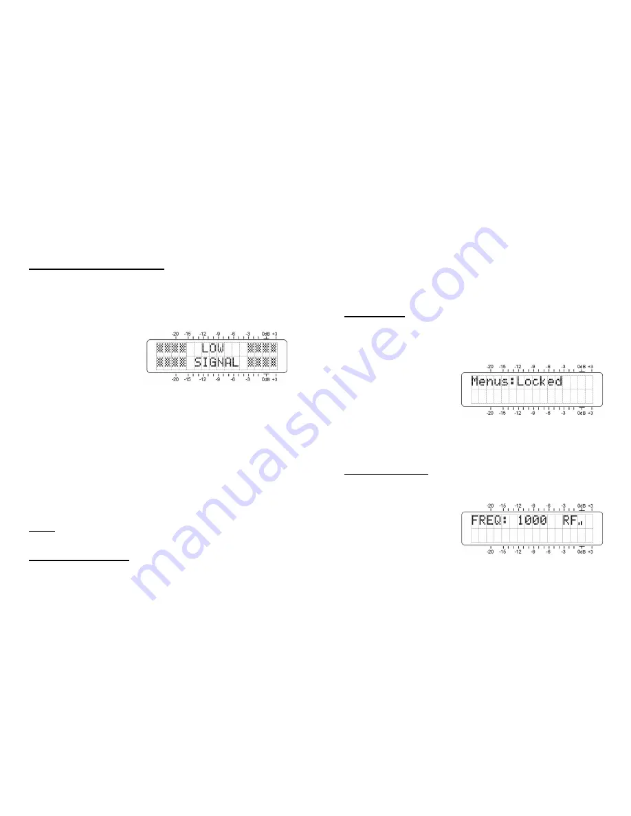
Tuning the Receiver
(Menu Screen 1)
When power is applied to the 634 receiver, a ‘splash screen’
with the product ID pops up immediately on the LCD. With-
in a few seconds this will
revert to Menu Screen 1,
shown here as it might
appear when the receiver
is first powered-up, but
before it has been pro-
grammed.
Push the knob and
FREQ
will begin to blink. Now the receiv-
er may be tuned by turning the knob. A series of bars to
the right of
RF
will give a rudimentary display of incoming
carrier strength.


