18
RUN
ERR
SF
II
I
0 1 2 3
7
6
5
4
3
0 1
4 5 6 7
2
4 5 6 7
3
2
1
0
BF
RUN STOP
C
N
4 E
th
erC
A
T
C
N
3 E
th
erN
E
T
C
N
1 R
S
48
5
MFK
AM600-CPU1608TN
C
N
2 C
A
N
C
N
5
35
36
2
1
CANRUN
CANERR
5
4
1
2
3
9
8
7
6
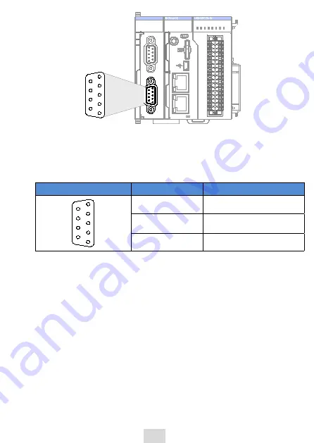
Figure 8 CANopen terminal on CPU module
3)
Wiring
CANopen requires a DB9 connector for data transmission. DB9 connector pins are
defined as follows:
Diagram
Pin
Definition of signal
5
9
4
1
2
3
8
7
6
PIN2
CANL
PIN7
CANH
PIN3
GND
Use shielded twisted pair cable to connect CAN bus, and attach a 120 Ω
termination resistor to each end of the bus to prevent signal reflection. Reliable
single-point grounding is often used for shield. Do not bind the cable together
with DC cable, high voltage cable, and so forth, so that communication signal will
not be interfered.
5.4 Serial communication connection through RS485
The CPU module provides a CN1 terminal as the RS485 port, as shown in the
following figure.


