background image


Using the Diagnostic Tool 


CODE RETRIEVAL PROCEDURE 


6  


CODE RETRIEVAL PROCEDURE 

Never

 replace a part based only on the DTC definition. Each DTC has a 

set of testing procedures, instructions and flow charts that must be 
followed to confirm the location of the problem. This information is found 
in the vehicle's service manual. Always refer to the vehicle's service 
manual for detailed testing instructions. 

Check your vehicle thoroughly before performing any test.  
 

ALWAYS

 observe safety precautions whenever working on a 

vehicle. See Error! Reference source not found. on page 1 for 
more information. 

1.


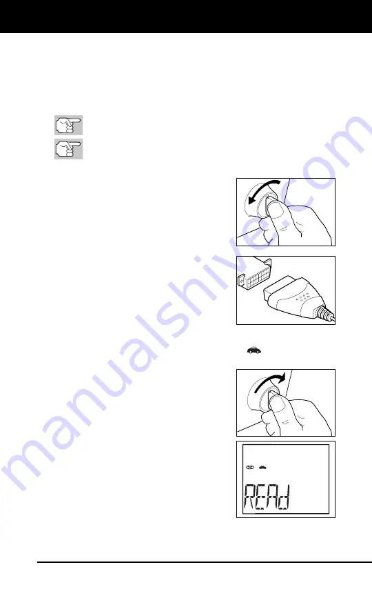
Turn the ignition off. 

2.


Locate the vehicle's 16-pin Data Link 
Connector (DLC). 

3.


Connect the Diagnostic Tool’s cable 
connector to the vehicle's DLC. The 
cable connector is keyed and will only fit 
one way. 

„


If you have problems connecting the 
cable connector to the DLC, rotate 
the connector 180° and try again. 

If you still have problems, check the 
DLC on the vehicle and on the 
Diagnostic Tool. Refer to your 
vehicle's service manual to properly 
check the vehicle's DLC. 

„


After the Diagnostic Tool’s test connector is properly connected 
to the vehicle's DLC, the Vehicle icon 

 should display to 

confirm a good power connection. 

4.


Turn the ignition on. 

DO NOT

 start the 

engine. 

5.


The Diagnostic Tool will automatically 
link to the vehicle’s computer(s). 

„


The LCD display will show "

rEAd

.” If 

the LCD display is blank, it indicates 
there is no power at the vehicle's 
DLC. Check your fuse panel and 
replace any burned-out fuses. 

If replacing the fuse(s) does not correct 
the problem, see your vehicle's repair 
manual to locate the proper computer 
(PCM) fuse/circuit. Perform any 
necessary repairs before continuing. 

„


After 4-5 seconds, the Diagnostic Tool will 

retrieve

 and 

display


any Diagnostic Trouble Codes that are in the vehicle's computer 
memory. 

Summary of Contents for CarScan 5030

Page 1: ......

Page 2: ...T THE DIAGNOSTIC TOOL CONTROLS AND INDICATORS 2 DISPLAY FUNCTIONS 3 USING THE DIAGNOSTIC TOOL CODE RETRIEVAL PROCEDURE 6 VIEWING ABS DTCs 8 VIEWING SRS DTCs 9 ERASING DIAGNOSTIC TROUBLE CODES DTCs 10 WARRANTY AND SERVICING LIMITED ONE YEAR WARRANTY 13 SERVICE PROCEDURES 13 ...

Page 3: ...ly moving objects Engine parts become very hot when the engine is running To prevent severe burns avoid contact with hot engine parts Before starting an engine for testing or troubleshooting make sure the parking brake is engaged Put the transmission in park for automatic transmission or neutral for manual transmission Block the drive wheels with suitable blocks Connecting or disconnecting test eq...

Page 4: ...e s computer and resets Monitor status 3 ABS button retrieves DTCs from the vehicle s Anti Lock Brake System ABS controller scrolls the LCD display to view DTCs when more than one DTC is present 4 SRS button retrieves DTCs from the vehicle s Supplemental Restraint System SRS controller scrolls the LCD display to view DTCs when more than one DTC is present 5 GREEN LED Indicates that all engine syst...

Page 5: ...MONITOR STATUS field Identifies the I M Monitor status area 2 Monitor icons Indicate which Monitors are supported by the vehicle under test and whether or not the associated Monitor has run its diagnostic testing Monitor status When a Monitor icon is solid green it indicates that the associated Monitor has completed its diagnostic testing When a Monitor icon is flashing red it indicates that the v...

Page 6: ...n the vehicle s computer for the currently displayed DTC 10 PENDING icon Indicates the currently displayed DTC is a Pending code 11 PERMANENT icon Indicates the currently displayed DTC is a Permanent code 12 DTC Display Area Displays the Diagnostic Trouble Code DTC number Each fault is assigned a code number that is specific to that fault 13 Code Number Sequence The Diagnostic Tool assigns a seque...

Page 7: ... Indicates communication status with a compatible Innova mobile application please visit www innova com apps for more information A solid blue icon indicates an active Bluetooth connection has been established A solid grey icon indicates Bluetooth is not connected ...

Page 8: ... problems connecting the cable connector to the DLC rotate the connector 180 and try again If you still have problems check the DLC on the vehicle and on the Diagnostic Tool Refer to your vehicle s service manual to properly check the vehicle s DLC After the Diagnostic Tool s test connector is properly connected to the vehicle s DLC the Vehicle icon should display to confirm a good power connectio...

Page 9: ...hicle are active and are performing their diagnostic testing and no trouble codes are present A zero will show on the Diagnostic Tool s LCD display for further confirmation Yellow LED Indicates one of the following conditions PENDING CODE PRESENT If the yellow LED is lit it may indicate the existence of a pending code Check the Diagnostic Tool s LCD display for confirmation A pending code is confi...

Page 10: ...rieved DTC has been displayed and the DTC FF button is pressed the Diagnostic Tool returns to the Priority code Visit the manufacturer s website for Fault Code Definitions Match the retrieved DTC s with those listed Read the associated definition s and see the vehicle s service manual for further evaluation VIEWING ABS DTCs ABS functionality is supported for Chrysler Ford and GM vehicles only Visi...

Page 11: ...nd turn the ignition On If the Diagnostic Tool is already connected and linked to the vehicle s computer proceed directly to step 3 If not continue to step 2 2 Perform the Code Retrieval procedure as described on page 6 3 Press the SRS button After 4 5 seconds the Diagnostic Tool will retrieve and display any Diagnostic Trouble Codes stored in the SRS controller s memory If SRS functionality is no...

Page 12: ...ol is already connected and linked to the vehicle s computer proceed directly to step 4 If not continue to step 2 2 Turn the ignition on DO NOT start the engine The Diagnostic Tool will automatically link to the vehicle s computer To erase OBD2 DTCs Wait until the codes are displayed on the Diagnostic Tool s LCD and then proceed to step 3 To erase ABS or SRS DTCs Press the ABS or SRS button as des...

Page 13: ... the problem s that caused the code s to be set If proper repairs to correct the problem that caused the code s to be set are not made the code s will appear again and the check engine light will illuminate as soon as the vehicle is driven long enough for its Monitors to complete their testing ...

Page 14: ...Notes 12 ...

Page 15: ...d or if the product was altered or repaired by anyone other than the Manufacturer s Service Center The Manufacturer under no circumstances shall be liable for any consequential damages for breach of any written warranty of this unit This warranty gives you specific legal rights and you may also have rights which vary from state to state This manual is copyrighted with all rights reserved No portio...

Page 16: ...1038 ...

Reviews: