background image

6

LIFELINE KIT / 180212 / www.innotech.at

EN

1x

2x

8x

1x

H.1

H.2

H.3









1x

G.1

G.2

G.3

1x

1x

OPTIONAL:

E

G

I

D

H

4

COMPONENTS/MATERIAL

B

A

1x

1x

2x

1x

I.1

I.2

I.3

1x

I.4

C

F









F.1

F.2

F.3

1x

1x

2x

1x

J

K

L

Summary of Contents for LIFELINE-KIT

Page 1: ...ndido las instrucciones de uso en el idioma del pa s ES PT ATEN O O uso do produto INNOTECH apenas permitido depois de ter lido e compreendido na totalidade as instru es de uso na respetiva l ngua nac...

Page 2: ...9 7 WARRANTY 10 8 APPROVAL 11 9 SIGNS MARKINGS 11 10 DIMENSIONS 12 11 INSTALLATION INSTRUCTIONS 12 12 INSTALLATION SUBSTRUCTURE 13 13 INSTALLATION TOOLS 13 14 INSTALLATION 14 15 FALL HEIGHT 22 16 WAS...

Page 3: ...death For a POTENTIALLY dangerous situation that can cause serious physical injuries or death For a POTENTIALLY dangerous situation that could lead to minor physical injuries and damage to property W...

Page 4: ...anchorage point in such a way that none can fall over the edge if the personal protective equipment is used properly See planning documents on www www innotech at Safety harnesses and the length of t...

Page 5: ...anchorage device in the event of strain Manufacturer s specifi cation of the personal protective equipment used including deflection of the cable body height 1 m safety margin Correct use of the indi...

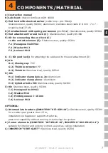
Page 6: ...6 LIFELINE KIT 180212 www innotech at EN 1x 2x 8x 1x H 1 H 2 H 3 1x G 1 G 2 G 3 1x 1x OPTIONAL E G I D H 4 COMPONENTS MATERIAL B A 1x 1x 2x 1x I 1 I 2 I 3 1x I 4 C F F 1 F 2 F 3 1x 1x 2x 1x J K L...

Page 7: ...nd attachment D G Kit G 1 Closing cap PVC G 2 Thimble retractor PP G 3 Thimble Stainless steel quality SS316 H Kit H 1 Indicator clamp below 2x Aluminium H 2 Indicator clamp above Aluminium H 3 Cylind...

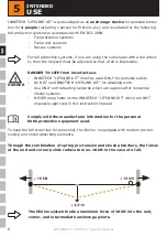
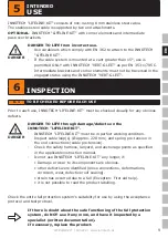
Page 8: ...2008 Fall ptotection systems Fall arrest systems Rescue systems Comply with the manufacturer information for the personal bbbb protective equipment used DANGER TO LIFE from incorrect use INNOTECH LIFE...

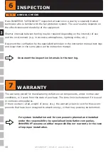
Page 9: ...harness lanyard and anchorage points as specified in the applicable instruction manual Do not use INNOTECH LIFELINE KIT any longer if Damage or wear to its components are obvious other defects were i...

Page 10: ...verification by the specialist technician in the instruction manual test logs and keep them in the same place as the instruction manual The warranty period for manufacturing defects on all components...

Page 11: ...n DIN EN 795 2012 www dekra siegelde Anschlageinrichtungen DIN EN 795 2012 www dekra siegelde JJJJ JJJJ JJJJ 19 20 21 22 2 3 19 20 21 22 2 3 19 20 21 22 2 3 8 APPROVAL INNOTECH LIFELINE KIT has been t...

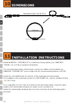
Page 12: ...LINE KIT must comply with the requirements specified in EN 795 Install the end attachments D and E at the anchorage points provided For installation onto anchorage points e g EAP STABIL 10 use the ind...

Page 13: ...able installation substructure Install INNOTECH LIFELINE KIT anchorage points in a statically load bearing installation substructure e g solid concrete with a minimum concrete quality of C20 25 DO NOT...

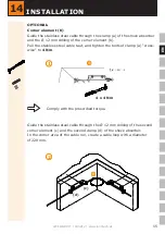
Page 14: ...TALLATION 2 The stud bolt should project approximately 4 thread turns beyond the lock nut 2x 4 Bolt the end lock C and the end attachment E together using the kit F 1 For installation onto anchorage p...

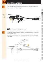
Page 15: ...nt b Pull the stainless steel cable taut and tighten the bolts of clamp a cross wise to 4 Nm 14 INSTALLATION 1 d a b Comply with the prescribed torque Guide the stainless steel cable through the 12 mm...

Page 16: ...steel cable in clamp d by tightening the bolts to 4 Nm 3 Comply with the prescribed torque 4 x 4 Nm K OPTIONAL Intermediate bracket J Guide the stainless steel cable through the intermediate bracket...

Page 17: ...nt and pre tension to a maximum force of 50 to 80 kg 3 14 INSTALLATION Thread the indicator clamp H and the thimble retractor G 2 onto the stainless steel cable At a distance of 120 mm from the end at...

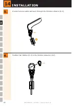
Page 18: ...18 LIFELINE KIT 180212 www innotech at x EN x Position the thimble G 3 in the thimble retractor G 2 Guide the loose cable end back through the thimble retractor G 2 6 5 14 INSTALLATION G 2 H G 3...

Page 19: ...4 INSTALLATION 8 7 Pull taut the cable loop and thimble G 3 into the thimble retractor G 2 Use a few hammer taps plastic mallet on the pre tensioned cable thimble within the cable loop to push the cab...

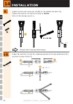
Page 20: ...directly to the thimble retractor G Tighten the bolts in the end lock clamp to 10 Nm Push on the closing cap G 1 10 9 Guide the end lock C into the retaining bracket of the end attachment D and bolt...

Page 21: ...on at the end attachment using the tension nut and counter nut 14 INSTALLATION 11 Spring length after tensioning between 80 125 mm 80 mm By checking the spring length the effect of a previous fall can...

Page 22: ...358 Through the correct use of the appropriate lanyards or fall arresters a fall ptotection system prevents a free fall Keep the connection to the anchorage system as short as possible Designation If...

Page 23: ...x cable deflection for LIFELINE KIT 2 5 m C the fall height specified by the manufacturer of the fall ptotection system as per EN 363 depending on the type of system used this can range from 0 5 m to...

Page 24: ...n for sheet metal roofs roof manufacturer profile material sheet metal thickness etc Date Location Dowel type BEF Sticker Designation Setting depth mm Drill bit mm Tightening torque Photos storage loc...

Page 25: ...o the client building owner and have been made available to the user At the access to the safety system the building owner must document the positions of the anchorage devices by means of diagrams e g...

Page 26: ...m showing the position of the anchorage devices Mark non shatter proof areas e g skylights and or light strips The maximum limit values of the safety system are provided in the relevant instruction ma...

Page 27: ...address INSPECTION POINTS checked and in order DEFECTS DETECTED Description of defects measures DOCUMENTATION Instruction manual Inspection logs Fastener documentation Photo documentation PPE persona...

Page 28: ...o deformation Screw connections secured Damage to plastic components Screw torque for shock absorber 4 x 4 Nm Cable loops approx 220 mm Screw torque of bolts for end lock clamp 8 x 10 Nm Cable pre ten...

Page 29: ...29 EN LIFELINE KIT 180212 www innotech at 20 DEVELOPMENT SALES INNOTECH Arbeitsschutz GmbH Laizing 10 4656 Kirchham Austria www innotech at...

Page 30: ...30 LIFELINE KIT 180212 www innotech at EN 21 SYSTEM VARIANTS 15 m E C F D...

Page 31: ...31 EN LIFELINE KIT 180212 www innotech at 21 SYSTEM VARIANTS a b c d 15 m 15 m a b c d D K K J J K K E C F...

Page 32: ...32 LIFELINE KIT 180212 www innotech at EN 22 ATTACHMENT 29 mm...

Page 33: ...33 EN LIFELINE KIT 180212 www innotech at 22 ATTACHMENT 45 mm...

Reviews: