background image

Rely on more Senses - www.innosent.de   |   21 


iSYS-5005 User Manual 

10.6. Configuration Wizard 

Before you start configuring your application, you should select the appropriate mode (for security & door opener applica-
tion). You can find the selection on the right side of the Object Viewer start screen.  

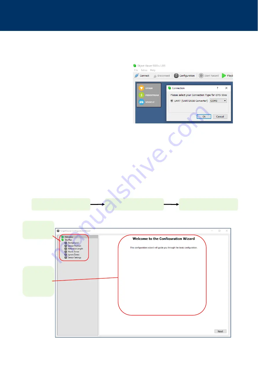
The iSYS-5005 can be easily configured using the Object Viewer. Open the Configuration Wizard by clicking on the 
’Configuration’ button. Here you will be guided through all steps necessary to configure the iSYS-5005 for your application. 
Below, the welcome screen and the overview of the configuration process are shown. With ‘Next’ you can navigate through 
the different configuration menus. 

Overview of con-
figuration menus 

Main window to 
set background, 
position, sensor 
and zone settings 

Connect to iSYS-5005 

Configure measurement scene 

Send Configuration to Sensor 

10.5. Connect to iSYS-5005 Evaluation Kit 

If the Object Viewer is not already connected to the iSYS-5005 Evaluation Kit, establish a connection by clicking on the 
‘Connect’ button.  

 

Select a connection type to the iSYS-5005 Evaluation 
Kit. Usually via UART/USB.  

Fig. 12: Object Viewer Connect iSYS-5005 

Fig. 13: Object Viewer Configuration Wizard 

Summary of Contents for iSYS-5005

Page 1: ...Rely on more Senses www innosent de1 iSYS 5005 Evaluation Kit User Manual...

Page 2: ...eight and Mounting Angle 14 08 Connecting 16 8 1 Connector Placement 16 8 2 Power Supply 16 09 Communication 17 9 1 Read Write Configuration 17 9 2 Object List 18 10 Configuration using Object Viewer...

Page 3: ...7 View Settings 26 10 8 Object List Object Viewer 27 10 9 Save Configuration 27 10 10 Record Playback 28 10 11 Update Firmware 29 10 12 Send Configuration to System 29 10 13 Read Configuration from S...

Page 4: ...www innosent de 4 iSYS 5005 User Manual HISTORY Document revision Date Change log Author 1 2019 03 13 First release MD 1 1 2020 05 08 Update Installation Mounting Communication MD 1 2 2020 06 26 Firm...

Page 5: ...tion areas security or door opener The desired mode can easily be changed by a sent command or in the Object Viewer software The measurements contain range radial speed azimuth angle and received sign...

Page 6: ...horizontal 75 vertical 30 velocity range mode A 0 87 55 08 km h mode B 0 44 27 54 km h range resolution dres 0 9 m velocity resolution mode A vres 0 87 km h mode B vres 0 44 km h angular resolution 4...

Page 7: ...sfully monitor his applications The object list is de scribed in the section 9 2 Object List User Own Evaluation User Specific Applications Object List Object lists have to be requested by the Radar A...

Page 8: ...rn Red graph elevation angle Green graph elevation angle TX antenna pattern TX 1_Elevation TX 2_Elevation 3 dB Width 67 66 10 dB Width 110 111 Red graph azimuth angle Green graph azimuth angle TX ante...

Page 9: ...is a micro USB interface on it Radome The iSYS 5005 Evaluation kit is supplied with a radome This can be considered as a design recommendation Software Package can be downloaded from InnoSenTs downlo...

Page 10: ...Manual 4 MECHANICAL DRAWING The illustrations show the mechanical drawings of the iSYS 5005 as a series product Fig 2 Mechanical drawing frontside iSYS 5005 series product Fig 3 Mechanical drawing ba...

Page 11: ...use the voltage given in the manual Do not wire any connections while power is applied to the device Ground the devices carefully to prevent electrical shock All connectors are pin coded and fit in on...

Page 12: ...exe and follow the instructions of the installation on your windows PC 2 Step Mount the iSYS 5005 sensor in a stationary position for example on a tripod Align the sensor in one direction The sensor i...

Page 13: ...ct such as ID velocity position is displayed in the object list in the lower area of the software 6 Step Congratulations You have just started your iSYS 5005 Evaluation Kit Sensor System The easy inst...

Page 14: ...6 Typical security application 7 1 Recommended Installation Height and Mounting Angle The installation height recommended by us and the mounting angle are to be considered as recommendations These hav...

Page 15: ...e Senses www innosent de 15 iSYS 5005 User Manual Door opener application installation symbol min typ max unit height h 2 0 6 5 2 1 6 8 2 5 8 2 m ft mounting angle 40 45 50 Fig 7 Typical door opener a...

Page 16: ...not connect 6 DNC Do not connect 7 DNC Do not connect 8 DNC Do not connect 9 DNC Do not connect 10 DNC Do not connect 8 2 Power supply PARAMETER SYMBOL MIN TYP MAX UNITS Suppy voltage VCC 3 3 5 5 V Su...

Page 17: ...RadarAPI_readMe pdf Read object list Read configuration data Write configuration data iSYS 5005 Customer PC 9 1 Read Write Configuration For a proper signal processing the configuration must be set ca...

Page 18: ...esian coordinates measured in meters Position y m Distance the Track has to the sensor in Y direction Cartesian coordinates measured in meters Velocity in direction m s Velocity the Track has in its d...

Page 19: ...w innosent de downloadportal Please ask your InnoSenT contact for information on how to receive the software package Open the Object Viewer folder in the software package and install Object Viewer5005...

Page 20: ...ch easier In Record Mode the video stream from the camera is stored together with the radar data on the hard disk Therefore it is possible to evaluate data offline Note It is important to connect to t...

Page 21: ...iSYS 5005 for your application Below the welcome screen and the overview of the configuration process are shown With Next you can navigate through the different configuration menus Overview of con fig...

Page 22: ...ensor and defining the event zones for your application Option 1 Load a jpg file or png file from the hard drive Option 2 Open Google Maps with the built in Mapviewer just click the Map button and tak...

Page 23: ...Object Viewer needs a reference length in the background image If the length is not set correctly measured objects and radar coverage do not match to the image As a consequence the set alarm or ignore...

Page 24: ...be added in the Alarm Zone Menu Afterwards the desired zone type can be selected Place the Alarm Zone in the background image The shape of the Alarm Zone can be adjusted by placing its nodes Double cl...

Page 25: ...Note Already existing tracks can move through an Ignore Zone without being harmed Place an Ignore Zone in the background image The shape of the Ignore Zone can be adjusted by placing its nodes Double...

Page 26: ...aulty tracks The End of Sight setting enables an individual configuration of the detection range of the sensor This will hide any tracks that occur outside the selected range The preferred setting mus...

Page 27: ...approaching 10 9 Save Configuration When you have finished configuring the iSYS 5005 Evaluation Kit it is recommended to save the settings to a file on your PC This can be done in the File Menu of the...

Page 28: ...on going tracks objects and video stream can not be observed To play back recorded data click the Playback button and select the appropriate data file Attention After loading recorded data from a file...

Page 29: ...he firmware update 10 12 Send Configuration to System When you have finished configuring the iSYS 5005 Evaluation Kit press the Send Configuration to System button Now all selected configurations are...

Page 30: ...h overview For details please contact the local approval agencies An overview over the frequency bands in Europe can be found in the REC 70 03 Annex 6 which is available under www cept org FREQUENCY B...

Page 31: ...ording to the European Community Directive 2012 19 EU on waste electrical and electron ic equipment Devices must not be disposed of with consumer waste For environmentally compatible recycling and dis...

Page 32: ...al here at InnoSenT We therefore offer direct support for our customers Please send your questions feedback and recommendations concerning iSYS 5005 to the e mail sales innosent de InnoSenT GmbH Am Ro...

Reviews: