


4
IN3552R / IN3562R OPERATION MANUAL - REV. 1.0 11/27/99
©1999 - INLINE, INC.
OPERATION
Input Selection
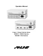
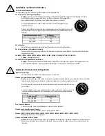
The IN3552R / IN3562R two input switchers provide a front panel button which may be used to select
the desired input channel. Each time the SELECT button is pressed the unit toggles back and forth
between Input 1 and Input 2 and the appropriate front panel LED indicator lights to show the current
channel selection. The non-selected channel is terminated into 75 Ohms. The switcher automatically
returns to the last selected channel if power is removed and reapplied to the unit. Input channels may also
be selected remotely by using a wired remote or a third-party control system (see Remote Control
Operation below for more details).
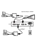
Since the IN3552R / IN3562R switchers are passive, they are also bi-directional, meaning that signals
may pass backwards through the unit. In such an installation, a single source signal is hooked up to the
OUTPUT connector and two display devices are attached to the INPUT connectors. When an input is
selected, the source signal is routed to one of the attached display devices.
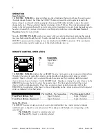
REMOTE CONTROL OPERATION
PIN
FUNCTION
1
Input Select
2
Ground
3
Status
The IN3552R / IN3562R switchers have a REMOTE port, a 3-pin captive screw connector which allows
the units to be remotely controlled and also provides feedback to indicate which input is currently
selected. Input 1 or Input 2 can be selected through the remote port by providing a latching contact
closure between the pin 1 and pin 2 on the REMOTE jack. Opening or closing the contact closure on the
REMOTE jack causes the unit to select the opposite input. The front panel switch and the contact
closure switch work independently. Therefore, an open or closed status between pins 1&2 on the
REMOTE port could select either Input 1 or Input 2 depending on the current position of the front panel
switch as indicated in the chart below.
Pin 1 & Pin 2 - No Connection
Pin 1 Grounded to Pin 2
Front Panel Button - Out
Input 2 Selected
Input 1 Selected
Front Panel Button - Depressed
Input 1 Selected
Input 2 Selected
Status Pin (Pin 3) -
The REMOTE connector status pin can be used to provide feedback to a control system to indicate
whether Input 1 or Input 2 is currently selected. The status pin will be high or low depending on the
current input:
Pin 3 High (5V) - Input 2 is currently selected
Pin 3 Low (0V) - Input 1 is currently selected


