


http://air.ingersollrand.com
1
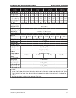
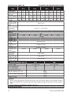
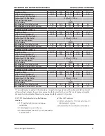
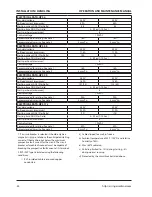
OPeRATIOn AnD MAInTenAnCe MAnUAL
GeneRAL InFORMATIOn
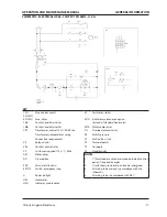
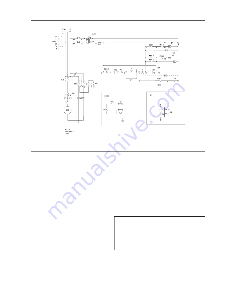
SCHeMATIC, eLeCTRICAL UP5 5–15HP SD 3PH 50Hz
KeY
1SV
Valve, solenoid (nc)
KM2-1,2
Contacts, auxiliary. Delta contactor
CR
Relay, control
KM
Contactor, star
CR-1
Contact, control relay
KM-1,2
Contacts, auxiliary. Star contactor
CS
Customer supplied 20v / 1 / 50hz
LT1
Light, power on indicator (green)
DM
Motor, dryer
LT2
Light, auto restart indicator (white)
DO
Dryer option
MIO
Indicator, maintenance option
EDV
Valve, electric drain
(Instead of standard hourmeter)
HATS
Switch, high air temperature
MOL
Overload, main motor
HM
Hourmeter
MOL-1
Contact, main motor overload
HM1
Indicator, maintenance
ST
Push button, start
MM
Motor, compressor
T1
Transformer, control
P
Switch, pressure
TM1
Relay, delta starting (10sec)
ES
Switch, emergency stop
TM1-1
Relay, delay off, contact
FU1, FU2
Fuse, primary
FU
Fuse, secondary
nOTeS
FU, FU5
Fuse, dryer
1.
(*) Furnished, mounted and wired outside of
control panel, if required by order.
KM1
Contactor, main
2.
Circuit shown in normal position de–energized.
KM-1,2,
Contacts, auxiliary. Main contactor
.
All wiring to be marked in accordance with this
schematic.
KM2
Contactor, delta
.
All wiring to be in accordance with NEC.


