

Ingersoll-Rand Architectural Hardware Limited, PO Box 19-347, Avondale 1746, 437 Rosebank Road, Avondale 1026, Auckland, New Zealand
Phone 0800 477 869, Fax 0800 477 868, Customer Service Email [email protected], Website www.ingersollrand.co.nz
Figure 1
Figure 1
8
8
8
1
3
3
2
6
7
Cylinder tailbar
Locator template
(A)
(C)
Cylinder tailbar
(A)
(C)
Locator template
(A)
(C)
(B)
3
1
SlamStop™ button
10
10
10
10
11
11
6
12
12
7
13
15
13
15
11
11
11
11
8
Striker
plate
8
Figure 2
SlamStop™ button
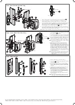
Step 4 External Pull And Lock Body Fixing
1 Remove internal handle
➀
from lock body
➂
by removing screw fixings
11
.
2 Locate external pull
➁
to external side of sliding door. For locking and
deadlocking models only, ensure the cylinder tailbar is in a vertical position.
3 Locate lock body
➂
to inside of sliding door. For locking and deadlocking models
only, you must first depress the
SlamStop™ button and activate the snib to
throw the locking jaws out before mounting to the stile. Secure lock body
➂
to
external pull
➁
with correct length taptite screws
10
provided.
4 To assist with engaging the cylinder tailbar into the lock body
➂
use the locator
template
➇
. Simply slide the locator template
➇
between fixing posts (A) and (C)
until it engages fully with the cylinder tailbar (Figure 1).
Note:
Remove locator template
➇
before securing lock body
➂
to external pull
➁
.
Step 6 Strike Installation
1 Remove striker cover
➆
from striker body
➅
.
2 Locate striker body
➅
onto door frame and secure with
screw fixings
12
provided.
3 Check striker body
➅
is centred on the lock body
➂
.
Adjust position if necessary by unscrewing adjustment
screws A and B and move up or down, re-tighten when
completed.
4 Close door and check locking operation of sliding door
lock. Difficulty in operation may result from
SlamStop™ button not being fully depressed.
To correct operation, open door and turn anti-clockwise
the strike adjustment screws A and B by one quarter
turn, now complete by turning strike adjustment screw
C anti-clockwise by one quarter turn.
Check lock operation and repeat striker adjustment
steps as required.
Note:
Care must be taken with adjustments to ensure the
striker plate is not bent by applying excessive force.
Figure 1
Figure 1
8
8
8
1
3
3
2
6
7
Cylinder tailbar
Locator template
(A)
(C)
Cylinder tailbar
(A)
(C)
Locator template
(A)
(C)
(B)
3
1
SlamStop™ button
10
10
10
10
11
11
6
12
12
7
13
15
13
15
11
11
11
11
8
Striker
plate
8
Figure 2
SlamStop™ button
Figure 1
Figure 1
8
8
8
1
3
3
2
6
7
Cylinder tailbar
Locator template
(A)
(C)
Cylinder tailbar
(A)
(C)
Locator template
(A)
(C)
(B)
3
1
SlamStop™ button
10
10
10
10
11
11
6
12
12
7
13
15
13
15
11
11
11
11
8
Striker
plate
8
Figure 2
SlamStop™ button
Step 5 Internal Handle To Lock Body Fixing
1 Locate internal handle
➀
onto lock body
➂
and secure
with screw fixings
11
provided.
2 For deadlocking models only, ensure the cylinder tailbar
is in a vertical position before attaching to lock body
➂
.
3 To assist with engaging the cylinder tailbar into the lock
body
➂
use the locator template
➇
. Simply slide the
locator template
➇
between fixing posts (A) and (C)
until it engages fully with the cylinder tailbar (Figure 1).
Note:
Remove locator template
➇
before securing internal
handle
➀
to lock body
➂
.
4 Check general locking function by first depressing
SlamStop™ button and activating snib to retract
jaws to the unlock position. For deadlocking models
only depress
SlamStop™ button and with key rotate
clockwise to check retraction of jaws. Turn key counter
clockwise until a full stop position is felt to engage
deadlocking function – snib is now inoperable. To
deactivate deadlocking function rotate key clockwise
until a full stop position is felt – snib is now operable.
For both functions, key must be rotated back to vertical
position to be removed.
Note:
Figure
➁
shows right hand internal handle. For left
hand internal deadlocking models, check general
locking function by reversing steps detailed in
step 4 above.
Figure 1
Figure 1
8
8
8
1
3
3
2
6
7
Cylinder tailbar
Locator template
(A)
(C)
Cylinder tailbar
(A)
(C)
Locator template
(A)
(C)
(B)
3
1
SlamStop™ button
10
10
10
10
11
11
6
12
12
7
13
15
13
15
11
11
11
11
8
Striker
plate
8
Figure 2
SlamStop™ button
Figure 1
Figure 1
8
8
8
1
3
3
2
6
7
Cylinder tailbar
Locator template
(A)
(C)
Cylinder tailbar
(A)
(C)
Locator template
(A)
(C)
(B)
3
1
SlamStop™ button
10
10
10
10
11
11
6
12
12
7
13
15
13
15
11
11
11
11
8
Striker
plate
8
Figure 2
SlamStop™ button
Figure 1
Figure 1
8
8
8
1
3
3
2
6
7
Cylinder tailbar
Locator template
(A)
(C)
Cylinder tailbar
(A)
(C)
Locator template
(A)
(C)
(B)
3
1
SlamStop™ button
10
10
10
10
11
11
6
12
12
7
13
15
13
15
11
11
11
11
8
Striker
plate
8
Figure 2
SlamStop™ button
Figure 1
Figure 1
8
8
8
1
3
3
2
6
7
Cylinder tailbar
Locator template
(A)
(C)
Cylinder tailbar
(A)
(C)
Locator template
(A)
(C)
(B)
3
1
SlamStop™ button
10
10
10
10
11
11
6
12
12
7
13
15
13
15
11
11
11
11
8
Striker
plate
8
Figure 2
SlamStop™ button
Figure 1
Figure 1
8
8
8
1
3
3
2
6
7
Cylinder tailbar
Locator template
(A)
(C)
Cylinder tailbar
(A)
(C)
Locator template
(A)
(C)
(B)
3
1
SlamStop™ button
10
10
10
10
11
11
6
12
12
7
13
15
13
15
11
11
11
11
8
Striker
plate
8
Figure 2
SlamStop™ button