


The electric chain hoist must be connected in accordance with supplied wiring
diagrams. Remove approximately 3/8 in. (9 mm) of the electrical power cable
protective casing to expose cable. Open the integrated clamp with a narrow blade
1/8 in. (3.5 mm) wide screw driver, Refer to Dwg. MHP3318 on page 6, and install
power cable end. Cables (leads) can be identified by color, or in the case of pendant
cables, by numbers taped to each cable. Terminals are identified by letters or labels
on the terminal blocks. Manufacturer-supplied cables have bare wire ends.
8-9 mm
(Dwg. MHP3318)
n
Ground (Earth) Connections
The power supply cord includes a grounding (earth) conductor (green wire). Ensure
grounding (earth) conductor is connected to the green/yellow connector terminal.
DANGER
•
The ground (earth), green or green/yellow wire, must not carry any power.
When hoist is supplied with a trolley, the power supply is connected at the
trolley relay box.
NOTICE
•
The ground (earth) connection must be wired to the green/yellow ground
(earth) connection terminal. Ground (earth) wire of the terminal power
supply is connected to the yellow/green wire (PE).
n
Direction of Movement Check
CAUTION
•
Hoist operation must be in accordance with the control pendant symbols.
If hoist does not operate in accordance with control pendant symbols then
hoist is mis-phased. Should this be the case, switch any two supply power
wires L1 and L2.
n
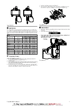
Load Chain
CAUTION
•
Only use original chains.
•
Welded seam of the chain links must face inward on the chain wheel (Refer
•
The geared limit switch must be mechanically disabled in order to install in
the chain, see section on “Limit Switch”.
1
2
(Dwg. MHP3319)
Before start-up and during its operation the load chain must be oiled along its full
length. The internal, contacting, and rubbing surfaces of the chain links must have
constant oil. Oiling can be effected by submersion or with an oil can, using a creeping
gear oil.
The end of the chain is to be affixed with a flexible piece of wire and fed through the
chain wheel (1) of the electric chain hoist. Through short switching impulses, the
Chain (2 ) will be housed correctly. Refer to Dwg. MHP3319 on page 6. The lifting
height must be dimensioned such that the hook fittings are on the ground in the
lowest hook position.
Single fall operation: The connection between the load hook (2) and the chain is
made with the hook block assembly (1). The last link must locate on the Pin (3). Apply
grease in the hook block recess (Refer to Dwg. MHP3320 on page 6).
1
2
3
(Dwg. MHP3320)
NOTICE
•
Pay attention to correct arrangement of suspension. (Refer to
Double fall operation:Connect load side of chain end to chain retainer (3) and fix
in housing guide rail. Assemble bottom sheave (1) with load hook (2). (Refer to
(Dwg. MHP3321)
NOTICE
•
Pay attention to correct arrangement of suspension. (Refer to
Dwg. MHP3322 on page 7). There must be no longitudinal chain
twisting. The chain end must be attached to the housing. (Refer to
Table 2:
Type of Hoist
Single Fall ‘k1’
Double Fall ‘k2’
QCH50
41.0
52 .0
QCH100
43.0
62 .0
QCH200
49.0
69.0
QCH300
49.0
69.0
QCH500
49.0
69.0
6
Form 04585147 Edition 6
Summary of Contents for QCH Series
Page 12: ...www ingersollrandproducts com...


