


TROUBLESHOOTING
This section provides basic troubleshooting information. Determination of specific causes to problems are best identified by thorough inspections performed by personnel
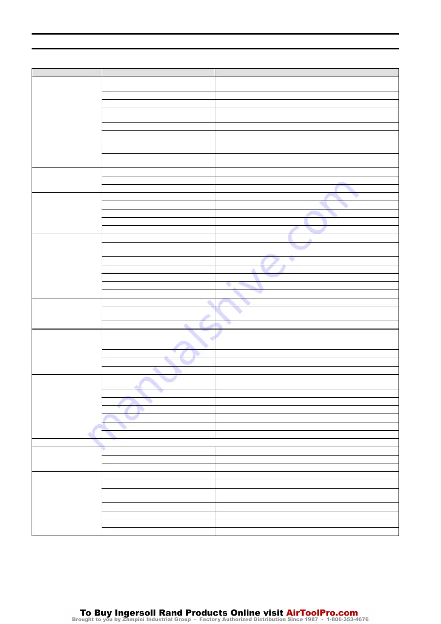
instructed in safety, operation and maintenance of this equipment. The chart below provides a brief guide to common winch symptoms, probable causes and remedies.
Symptom
Cause
Remedy
Hoist will not operate.
No air supply to hoist, or too little CFM or PSI.
Check PSI (bar) at hoist inlet. Refer to “SPECIFICATIONS” section in Product Information
Manual for correct CFM (cu.m/min) and PSI (bar).
Valve or limit arm sticking.
Check limit arm for free movement.
Emergency valve “OFF”.
Reset Emergency valve and push “ON” button.
Pendant malfunction.
Check PSI (bar) at pendant. Minimum operating pressure in pendant line is 55 PSI (380
kPa/3.8 bar).
Hoist is overloaded.
Reduce load to within rated capacity.
Motor is damaged.
Repair or replace. Refer to “MAINTENANCE” section on page 5. Check oil level in
motor and gearbox.
Lubricator is low on oil.
Fill lubricator.
Brake is not releasing (“DOWN” direction only).
Check brake release circuit and PSI (bar) at brake inlet (55 PSI (380 kPa/3.8 bar)
minimum).
Load continues to move when
hoist is stopped. “UP” direction.
Valve or limit arm sticking.
Check limit arm for free movement.
Dump valves not releasing.
Check pendant hose dump valves.
Pendant lever sticking.
Check lever and restore free movement.
Load continues to move when
hoist is stopped. “DOWN”
direction.
Valve or limit arm sticking.
Check limit arm for free movement.
Dump valves not releasing.
Check pendant hose dump valves (old style pendants).
Brake is slipping.
Check brake springs and brake disc linings for wear. Refer to “MAINTENANCE” section.
Hoist is overloaded.
Reduce load to within rated capacity.
Pendant lever sticking.
Check lever and restore free movement.
Hoist will not lift rated capacity.
Hoist is overloaded.
Reduce load to within rated capacity.
No air supply to hoist or too little CFM or PSI.
Check PSI (bar) at hoist inlet. Refer to “SPECIFICATIONS” section in Product Information
Manual for correct CFM (cu.m/min) and PSI (bar).
Main air valve travel is restricted.
Check limit arm and linkage for free movement.
Brake is not releasing.
Check brake release circuit and PSI (bar) at brake inlet (55 PSI (3.8 bar) minimum).
Exhaust is restricted.
Inspect vents and replace muffler.
Motor is damaged.
Check for worn motor bearings.
Motor or gearbox is out of oil.
Check oil levels in motor and gearbox. Fill to recommended level.
Hook can be lowered but not
raised.
Hoist is overloaded.
Reduce load to within rated capacity.
No air supply to hoist or too little CFM or PSI.
Check at hoist power supply connection with hoist under load. Raise pressure to rated
capacity.
Pendant malfunction.
Check PSI (bar) at air inlet connection (green fitting) on pendant.
Hook can be raised but not
lowered.
Brake is not releasing.
No breather in gearbox. Remove solid square head plug in outboard end of gearbox
only and install vented (breather) plug. Check PSI (bar) at brake inlet. (55 PSI (380 kPa/
3.8 bar) minimum.) Check brake and pendant dump valves, if used (old style pendants).
Brake piston seals leaking.
Install repair kit. Refer to Parts section.
Low air pressure.
Check PSI (bar) at valve inlet. Raise pressure to rated capacity.
Pendant malfunction.
Check PSI (bar) at yellow fitting connection on pendant.
Load chain jumps on sheave or
is making a snapping sound.
Worn or rusted chain.
Refer to “INSPECTION” section in Product Information Manual to determine wear limit.
Replace if necessary.
Incorrect chain.
Replace with correct chain.
Worn sheave or chain guide.
Replace worn parts.
Capsized hook.
Correct as described in “MAINTENANCE” section on page 5.
Hoist not in line with load.
Align hoist with load. Do not “yard” or “side pull.”
Incorrectly reeved load chain.
Check load chain is correctly reeved.
No oil on load chain.
Lubricate load chain.
Trolley (optional feature)
Trolley will not stop or trolley
wheels slip.
Damaged beam.
Repair or replace beam.
Excessive oil, grease or paint on track of beam.
Clean off oil, grease or paint.
Trolley not spaced for beam clearance.
Check trolley spacing. Refer to “INSTALLATION” section in Product Information Manual.
Air-powered trolley does not
operate.
Pendant lever sticking.
Check lever and restore free movement.
Emergency valve in “OFF” position.
Reset Emergency valve and push “ON” button.
No air supply to trolley or too little CFM (cu. m/min.)
or PSI (kPa/bar).
Check PSI (bar) at trolley inlet. Refer to manufacturer’s specifications.
Control valve is sticking.
Refer to “MAINTENANCE” section on page 5.
No oil in trolley motor or gearbox.
Check oil levels in trolley motor and gearbox and fill to required level.
Wheels are obstructed.
Remove obstruction.
Motor is damaged.
Repair or replace. Refer to “MAINTENANCE” section on page 5.
4
Form MHD56243 Edition 4


