


11
Air Supply
The air supply must be clean, free from moisture and lubricated
to ensure optimum motor performance. Foreign particles,
moisture and lack of lubrication are the primary causes of
premature motor wear and breakdown. Using an air filter,
lubricator and moisture separator will improve overall winch
performance and reduce unscheduled down time.
The air consumption is 380 scfm (10.8 cu. m/min) at rated
operating pressure of 90 psig (6.3 bar/630 kPa) at the winch
motor inlet. If air supply varies from recommended, then winch
performance will change.
Air Lines
The inside diameter of the winch air supply lines must be at least
1 inch (25.4 mm). Before making final connections, all air
supply lines should be purged with clean, moisture free air or
nitrogen before connecting to winch inlet. Supply lines should
be as short and straight as installation conditions will permit.
Long transmission lines and excessive use of fittings, elbows,
tees, globe valves etc. cause a reduction in pressure due to
restrictions and surface friction in the lines.
Air Line Lubricator
Refer to Dwg. MHP0191.
Always use an air line lubricator with these motors. The
lubricator must have an inlet and outlet at least as large as the
inlet on the motor directional control valve. Install the air line
lubricator as close to the air inlet on the motor as possible.
CAUTION
• Lubrication for the FA2A-GMR motor must be provided in
the supply air. Ensure an inline lubricator is installed before
operating the winch motor.
• Lubricator must be located no more than 10 ft. (3 m)
from the motor.
• Shut off air supply before filling air line lubricator.
The air line lubricator should be replenished daily and set to
provide 3 drops per minute of ISO VG 32 (10W) oil.
Air Line Filter
Refer to Dwg. MHP0191.
Place the strainer/filter as close as practical to the motor air inlet
port, but upstream from, the lubricator, to prevent dirt from
entering the motor. The filter/strainer should provide 20 micron
filtration and include a moisture trap. Clean the filter/strainer
periodically to maintain its operating efficiency.
(Dwg. MHP0191)
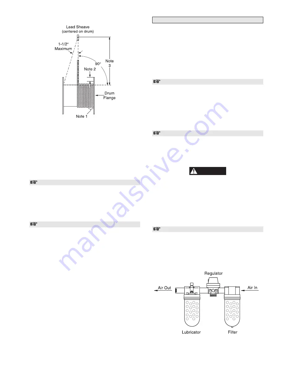
Wire Rope and Fleet Angle Installation Drawing
(Dwg. MHP0498)
Notes:
1.
Maintain a minimum of 4 tight wraps of wire rope on drum
at all times.
2.
Ensure wire rope does not exceed top layer requirement.
Refer to “SPECIFICATIONS” section.
3.
For correct fleet angle maintain a minimum of 1.6 feet (0.5
metre) per inch of drum length. Example: for 7 inch drum
length locate lead sheave at least 11.2 feet (3.5 metres)
from drum.
Rigging
Make sure all wire rope blocks, tackle and fasteners have a
sufficient safety margin adequate enough to handle the required
load under all conditions. Do not allow wire rope to contact
sharp edges or make sharp bends which will cause damage to
wire rope, use a sheave. Refer to the wire rope manufacturer's
handbook for proper sizing, use and care of wire rope.
Safe Installation Procedures
1.
Do not use wire rope as a ground (earth) for welding.
2.
Do not attach a welding electrode to winch or wire rope.
3.
Never run the wire rope over a sharp edge. Use a correctly
sized sheave.
4.
When a lead sheave is used, it must be aligned with the
center of the drum. The diameter of the lead sheave must be
at least 18 times the diameter of the wire rope. Refer to
Dwg. MHP0498.
5.
Always maintain at least four full, tight wraps of wire rope
on the drum.


