background image

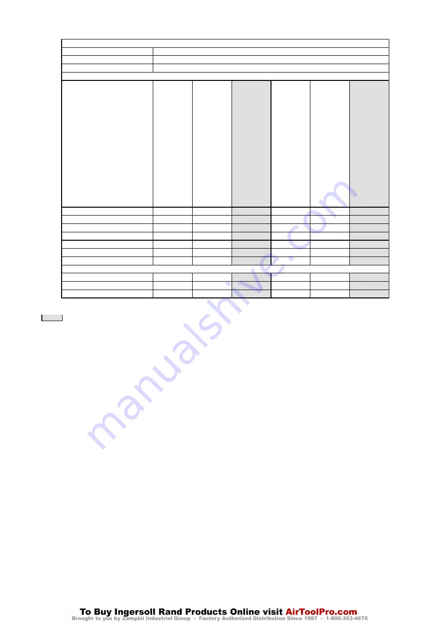
Table 3:  Decoking Winch Maintenance Interval Chart

The following work can be completed by owner maintenance personnel
System Air Filter

Inspect system air filter every 30 days or 100 hours

Grease Fittings

Lubricate grease fittings every 90 days or 250 hours

Gearbox Oil Level

Check oil level in gearbox every 90 days or 250 hours

It is recommended that the following work be completed by a trained Ingersoll Rand trained service technician.

Standard Components

1 year or

1,000 hrs

2 years or

2,000 hrs

3 years or

3,000 hrs

4 years or

4,000 hrs

5 years or

5,000 hrs

6 years or

6,000 hrs

Inspect Motor

X

X

Inspect Manual Band Brake

X

X

X

X

X

X

Inspect Disc Brake

X

X

Inspect Gearbox

X

X

Replace Winch Anchor Bolts

X

X

Rebuild Control Valve

X

X

Inspect Drum, Housings and Main Frames

X

X

X

X

X

X

Optional Components
Emergency Shut-Off Valve

X

X

X

X

X

X

Limit Switches

X

X

X

X

X

X

Automatic Band Brake *

X

X

X

X

X

X

*

Do not disassemble band brake air cylinder unless brake operation or visual inspection indicates a requirement.

NOTE: Hours are for actual winch drum rotation.


Recommend complete general overhaul.

Form MHD56375 Edition 2

3

Summary of Contents for FH5i-DCOKER

Page 1: ...Product Maintenance Information FORCE 5i Hydraulic Winch Model FH5i DCOKER Save These Instructions Form MHD56375 Edition 2 May 2012 43808922 2012 Ingersoll Rand...

Page 2: ...secure in drum d Verify wire rope diameter Measure the diameter of the wire rope from crown to crownthroughoutthelifeofthewirerope Recordingoftheactual diameter should only be done with the wire rope...

Page 3: ...ar or 1 000 hrs 2 years or 2 000 hrs 3 years or 3 000 hrs 4 years or 4 000 hrs 5 years or 5 000 hrs 6 years or 6 000 hrs Inspect Motor X X Inspect Manual Band Brake X X X X X X Inspect Disc Brake X X...

Page 4: ...condition contact the nearest Ingersoll Rand Distributor or the factory for technical assistance COMPONENT CONDITION CORRECTIVE ACTION NOTES Pass Fail Repair Replace Uprights and Siderails Drum Band B...

Page 5: ...Check up line flow controls are set as required to run the winch Relief valve dumps full pressure Confirm no down line restrictions of valves are blocking free flow back to tank Relief valve set too l...

Page 6: ...pin 102 at adjustment clevis 107 2 Pressurize brake cylinder 110 and remove pin 106 to disconnect clevis from brake lever 105 3 Turn adjustment clevis 107 clockwise to increase cylinder rod extension...

Page 7: ...with a soft faced hammer until assembly separates 11 Drive out pin 9 and remove coupling 14 from drive shaft 35 12 Remove seal adapter 10 from brake adapter 6 13 Remove O ring 5 and oil seal 2 from s...

Page 8: ...etary assembly 54 7 Align capscrew and dowel holes and install input housing 59 Apply a light coating of Loctite 262 to capscrew 60 threads and install by hand Equally tighten capscrews in a diametric...

Page 9: ...ere removed 8 Install brake adapter 6 on drum shaft 41 being careful not to damage O ring 33 Secure in position with capscrews 4 using Loctite 242 9 Lubricate and install O ring 5 on seal adapter 10 I...

Page 10: ...10 9 Dry Lubricated PTFE Dry Lubricated PTFE M6x1 9 10 6 7 4 11 12 8 9 5 6 M8x1 25 21 23 16 18 9 11 26 30 20 22 12 13 M10x1 5 41 47 31 35 19 21 53 60 39 45 24 27 M12x1 75 71 81 54 61 32 36 91 103 68 7...

Page 11: ...Form MHD56375 Edition 2 11...

Page 12: ...www ingersollrandproducts com...

Reviews: