MAINTENANCE
WARNING
•
Never perform maintenance on the winch while it is supporting a load.
•
Before performing maintenance, tag controls:
WARNING - DO NOT OPERATE, EQUIPMENT BEING REPAIRED.
•
Only allow Ingersoll Rand trained Service Technicians to perform
maintenance on this winch.
•
After performing any maintenance on the winch, test winch to 125% of its
rated line pull at mid drum before returning to service. (Testing to more
than 125% of rated line pull may be required to comply with standards and
regulations set forth in areas outside the USA.)
•
Shut off air system and depressurize air lines before performing any
maintenance.
•
Do not use Trichloroethylene to clean parts.
•
Use of other than genuine Ingersoll Rand parts may result in safety hazards,
decreased performance and increased maintenance and may invalidate all
warranties.
n
General
Correct disassembly (to prevent loss or damage of good parts), repair, assembly,
testing and adjusting are critical to proper winch operation. Maintenance
procedures are technical in nature and require training and experience to
accomplish correctly. In addition, repair and testing require specialized equipment
that is not typically found at the winch-mounting site.
Proper use, inspections and maintenance increase the life and usefulness of your
Ingersoll Rand equipment. During assembly, lubricate gears, nuts, capscrews and
all machined threads with applicable lubricants. Use of antiseize compound and/or
thread lubricant on capscrew and nut threaded areas prevents corrosion and allows
for easy disassembly of components.
It is extremely important that anyone involved with maintaining the winch be
familiar with the servicing procedures of these winches and be physically capable
of conducting the procedures. These personnel shall have skills that include:
1. Proper and safe use and application of mechanics common hand tools as well
as special Ingersoll Rand or recommended tools.
2. Safety procedures, precautions and work habits established by accepted
industry standards.
Ingersoll Rand cannot know of, or provide all the procedures by which product
operations or repairs may be conducted and the hazards and/or results of each
method. If operation or maintenance procedures not specifically recommended by
the manufacturer are conducted, it must be ensured that product safety is not
endangered by the actions taken. If unsure of an operation or maintenance
procedure or step, personnel should place the product in a safe condition and
contact supervisors and/or the factory for technical assistance.
n
Maintenance Intervals
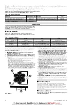
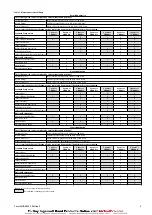
Refer to Table 3 ‘Maintenance Interval Chart’ on page 3 for recommended
maintenance schedule.
NOTICE
•
Refer to the Product Parts Information Manual for drawings unless
specified elsewhere.
n
Adjustments
n
Winch Guard
Refer to Dwg. MHP2676.
Winch guard panels must be adjusted to suit wire rope departure angle. Adjust per
procedures in Product Information Manual.
n
Disc Brake (optional feature)
Refer to Dwg. MHP2786.
Disc brake adjustment is not required. If disc brake does not hold rated load
disassemble and repair.
If brake assembly is removed or disassembled ensure breather (29) is installed and
located at top of brake housing during reassembly.
n
Manual Drum Band Brake
Refer to Dwg. MHP0209.
1. Release wire rope tension on drum.
2. Raise handle (104) to free brake bands (128).
3. Remove cotter pin (102) and pin (101).
4. Rotate link stud (103) clockwise to increase brake torque.
5. Install pin (101) and check adjustment.
6. Brake should be adjusted until brake lever over center position can be attained
with 50 to 100 lb. (23 to 45 kg) force on handle (104).
7. Install cotter pin (102) when adjustment is completed. Bend ends of cotter pin
over.
CAUTION
•
When any part of brake lining measures 0.062 inch (2 mm) or less, brake
bands (128) or linings must be replaced.
n
Automatic Band Brake (optional feature)
Refer to Dwg. MHP0209.
1. Remove cotter pin (102) at adjustment clevis (107).
2. Apply air to brake cylinder (110) and remove pin (106) to disconnect clevis from
brake lever (105).
3. Turn adjustment clevis (107) clockwise to increase cylinder rod extension. Turn
clevis counterclockwise to decrease cylinder rod extension.
4. Assemble clevis (107) to brake lever (105) with pin (106). Release air to brake
cylinder (110).
5. Measure cylinder rod extension. Length should be 1 to 1-1/2 inches (25 to
37mm). Re-adjust if necessary.
6. Install cotter pin (102) to secure clevis to brake lever when adjustment is
complete. Bend ends of cotter pin over.
7. With brake “On”, adjust screw (127) to just touch arm (124).
n
Pilot Air Control Valve (optional feature)
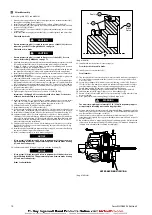
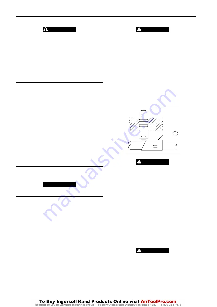
Refer to Dwgs. MHP2969 in the Product Information Manual and
Dwg. MHP1027 on page 6, A. Sleeve.
Valve is set at factory.
Sleeve
A
(Dwg. MHP1027)
CAUTION
•
Do not disassemble pilot cap assemblies. Valve cylinder and valve cap are
press fit together. Close fit tolerances cannot be maintained if
disassembled. If repair is required, replacement of the pilot cap assembly
is required.
If winch operating speeds differ from performance specifications, pilot air control
valve may require adjustment.
1. Lubricate threads and install capscrews (366) and (368), lockwashers (924),
gasket (340) and pilot cap assembly (367) to valve body (339). Tighten capscrew,
but do not torque.
2. Reaching into exhaust port on valve body (339), grasp shaft (331) and check for
movement in either direction. Any movement requires adjustment.
3. If there is shaft movement, remove pilot cap assembly and back out setscrews
in pistons 1/4 turn. Repeat until there is no movement.
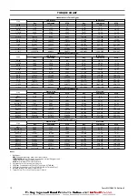
4. When adjustment is complete, tighten capscrews (366) and (368). Refer
to“TORQUE CHART” on page 12 for torque requirements.
n
Limit Switch (optional feature)
Refer to ‘Limit Switch Adjustment’ procedure in Product Information Manual Form
MHD56301.
n
Constant Tension (optional feature)
Refer to Dwg. MHP2028.
The regulator is preset at 0 psig (0 bar/0 kPa), therefore requires adjustment when
winch is installed. To adjust for specific load applications, regulator pressure may be
adjusted to increase or decrease tension setting.
Regulator gauge and regulator are accessible through cover.
WARNING
•
When adjusting regulator, ensure winch control lever is locked in neutral
position and tension selector lever is in the NORMAL position.
•
Winch supply air is NOT shut off during regulator adjustments. To prevent
accidental winch operation, allow only a single person, trained in
operation, safety and maintenance of this product, to conduct regulator
adjustments
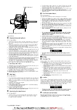
Regulator Adjustment Procedure:
Refer toDwg. MHP1865 on page 7.
6
Form MHD56303 Edition 2


