


10
MHD56114 - Edition 4
Wire Rope
CAUTION
• Maintain at least 3 tight wraps of wire rope on the drum at
all times. Refer to Dwg. MHP0498 on page 11.
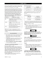
Standard and Open Frame (Face) Winch
Install the winch such that the wire rope, when at the take-off
angle limits, does not contact the mounting surface. Refer to Dwg.
MHP1013 on page 10.
WARNING
• Exceeding wire rope take-off angles will cause the wire rope
to come into contact with the winch frame supports resulting
in damage to the wire rope and winch.
Wire Rope Selection
Consult a reputable wire rope manufacturer or distributor for
assistance in selecting the appropriate type and size of wire rope
and, where necessary, a protective coating. Use a wire rope which
provides an adequate safety factor to handle the actual working
load and that meets all applicable industry, trade association,
federal, state and local regulations.
When considering wire rope requirements the actual working load
must include not only the static or dead load but also loads
resulting from acceleration, retardation and shock load.
Consideration must also be given to the size of the winch wire
rope drum, sheaves and method of reeving. Wire rope
construction must be EIPS 6 X 19 IWRC right lay.
Note:
To maintain 5:1 safety factor ratio 1/2 inch (13 mm) wire
rope must be used.
(Dwg. MHP1013)
Installing Wire Rope
Refer to Dwg. MHP0652 on page 11.
1.
Cut wire rope to length and fuse end to prevent fraying of
strands in accordance with the wire rope manufacturer's
instructions.
2.
Feed the end of the wire rope into the wire rope anchor hole
in the drum and pull through approximately three feet (1
metre) of wire rope.
3.
Forming a large loop with the wire rope, insert the end back
into the top of the anchor hole.
4.
Place the wire rope wedge into the wire rope anchor pocket in
the drum. Install the wedge such that the wire rope will wrap
around the wedge as shown in Dwg. MHP0652 on page 11.
5.
Pull the wire rope into position in the drum anchor pocket. Ensure
the wire rope is installed below the edge of the drum flange
diameter. Use of a copper drift or similar tool may be required to
fully insert wire rope and wedge into the anchor pocket.
CAUTION
• Make sure the first wrap of wire rope is tight and lays flush
against the drum flange.
• Ensure the correct wire rope anchor is used.
• Install wire rope to come off the drum in an overwind
position. Improper installation of wire rope can result in
failure of the disc brake to hold load. Refer to Dwg. MHP0652
on page 11.
Table 3 - Wire Rope Size
Wire Rope
Anchor
Part No.
Minimum
Maximum
inch
mm
inch
mm
25539
3/8
10
5/8
16


